IBASE MB839 User Manual
Page 18
INSTALLATIONS
12
MB839 Series User’s Manual
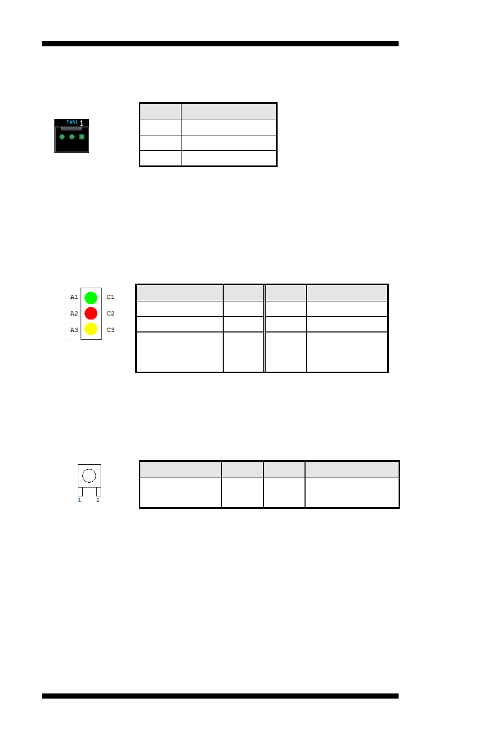
FAN1: System Fan Power Connector
Pin header for system fan. The fan must be 12V (Max. 1A).
Pin #
Signal Name
1
Ground
2
+12V
3
Rotation Control
LED1, LED2, LED3, LED4: LAN Port Link, Active LED
LED5: Status LED
A1 & C1 : Status LED
A2 & C2 : Bypass LED
A3 & C3 : Power LED
Signal Name
Pin #
Pin #
Signal Name
SIO_GP27
A1
C1
SIO_GP26
ALARM_R
A2
C2
BY_LED_R
PWR_R
A3
C3
GND
Index port: 4E
Data port: 4F
Device: 07
F5h bit5, bit6 (Control pin)
SW3: Software reset button
Signal Name
Pin #
Pin #
Signal Name
GND
1
2
Intel SoC
GPIO7
IO Base:
Read memory 0 x fed0e238 and set bit 1 to “1” as (GPI ),
set bit 1 to “0” as (GPO )
Read memory 0 x fed0e238 and check the bit 0 (Control Pin)
Note: SW3 is controlled by GPIO only.