IBASE MB839 User Manual
Page 19
Advertising
INSTALLATIONS
MB839 Series User’s Manual
13
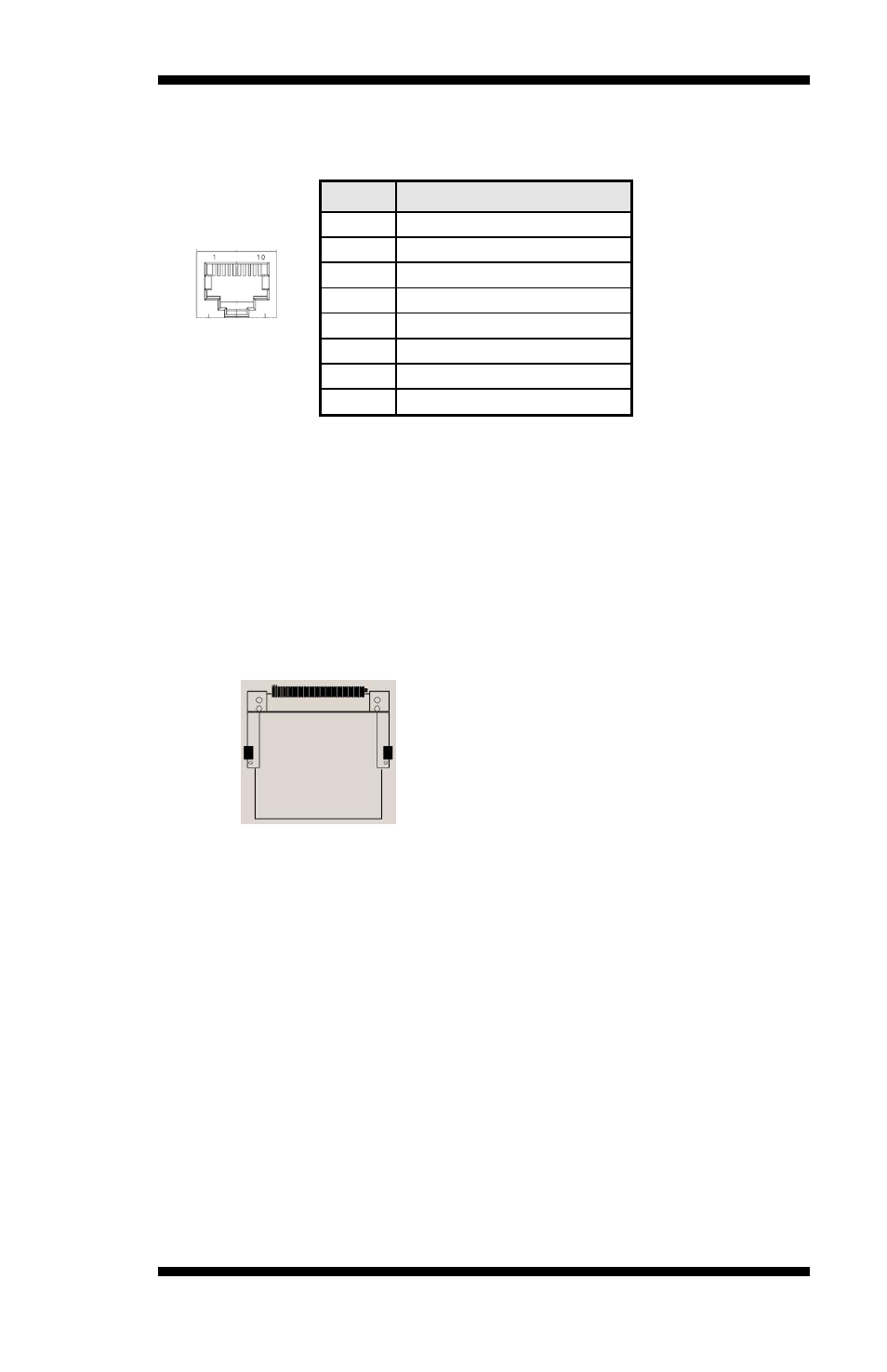
CN1: MicroSD Connector
CN2: Console Port (COM1)
Pin #
Signal Name (RS-232)
1
RTS, Request to send
2
DTR, Data terminal ready
3
TXD, Transmit data
4
Ground
5
Ground
6
RXD, Receive data
7
DSR, Data set ready
8
CTS, Clear to send
CN3: Serial ATA Port
CN4: USB2.0 Ports
CN5, CN6, CN7, CN8: LAN 1G / 100M Port
CN9: SO-DIMM DDR3 Socket
CN10: Compact Flash Connector
Note: CF card supports IDE mode only.
If CF card applied, please set the SATA configuration to “IDE
mode” in BIOS.
CN11: Mini PCI- E Connector (Half size)
CN12 : DC Power Jack (+12V only)
Note: CN12 and J10 cannot be connected at the same time.
Advertising