ikan IKW1-A User Manual
Page 9
Advertising
9
FIGURE 4
1) Infrared Remote Receiver
2) Link LED
a. LED light turns on when connection between transmitter and receiver
is confirmed.
3) Power LED
4) Battery LED
a. LED will blink when battery source is low.
5) Tally LED
a. Indicates Tally Control is in use.
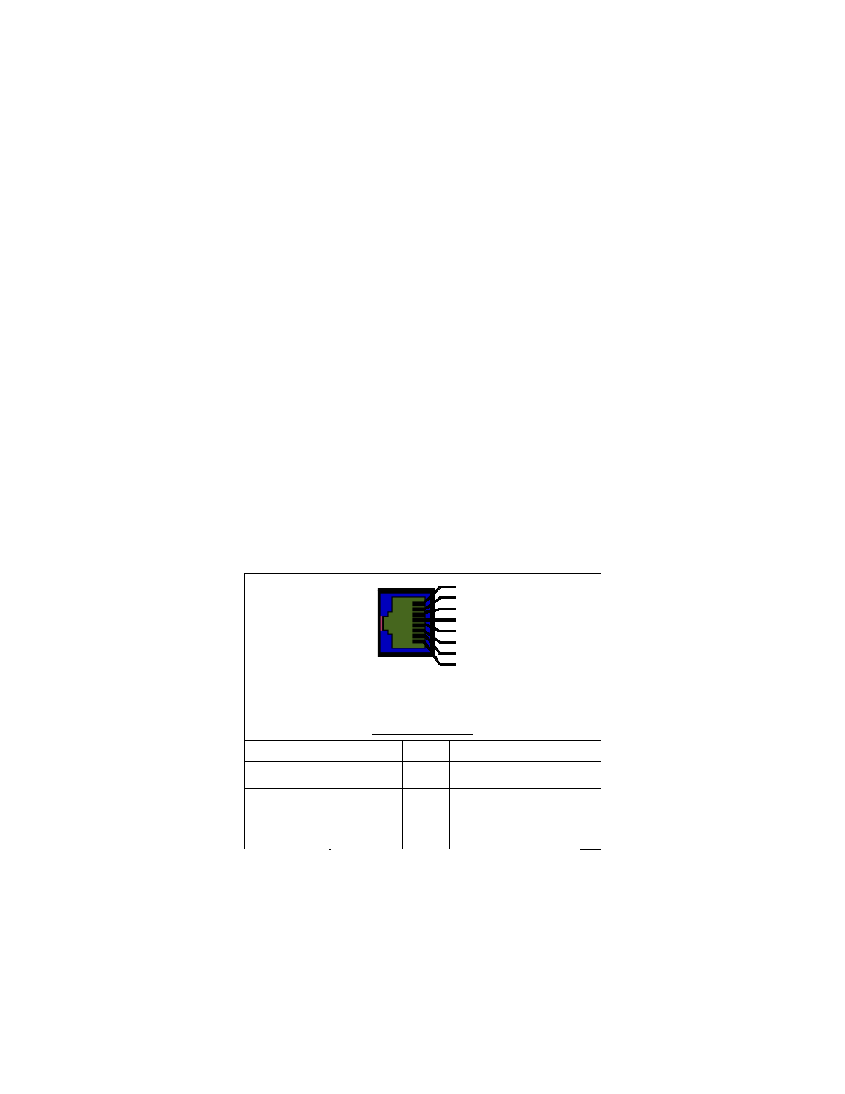
6) GPI Port (Remote RJ-45 Port)
a. This port is used to control the device through Ethernet cable
(FIGURE 5).
b. Pins 1 through 7 are control terminals, Pin 8 is GND terminal.
FIGURE 5
RJ-45 Pin Assignment
Remote PIN Assignment
1 PIN
GPI Port 1(NC)
5 PIN
GPI Port 5 (NC)
2 PIN
GPI Port 2
TALLY_ON_RED
6 PIN
GPI Port 6
(External Tally Green Out Only)
3 PIN
GPI Port 3 (NC)
7 PIN
GPI Port 7
(External Tally Red Out Only)
4 PIN
GPI Port 4 (NC)
8 PIN
COMMON(GND)
1
2
3
4
5
6
7
8
Remote (RJ-
45)
Advertising