Part 5. testing the repair, Part 6. final steps – Infloor Heating Cable Repair Kit User Manual
Page 4
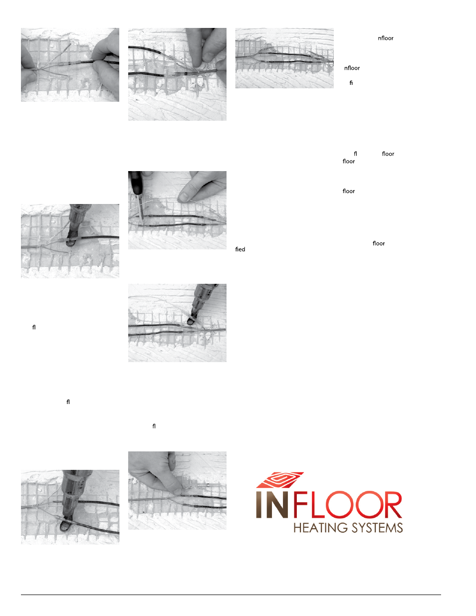
Step 4.15. Place the heating ele-
ments and black jumper wire ends
alongside each other. Lightly twist
the elements together to better join
them. Slide the solder tube over the
twisted elements and over the edge
of the insulation on the black jumper
wire. Make sure the twisted wires are
fully inside the solder tube and locat-
ed between the adhesive bands at
the ends of the solder tube. If this is
not done correctly, the elements may
pull out and cause the splice to fail.
Step 4.16. Use the heat gun (set
to HI temperature, about 1000°F) to
carefully heat the solder tube. First,
heat directly under the solder ring in
the middle of the tube. IMPORTANT!
When the solder completely melts
and ows into the wires, continue
heating for another 3 seconds. If the
heat is removed too soon, an incom-
plete solder connection will result
and cause connection failure later.
When the solder has completely
melted, begin moving the heat gun
back and forth under the rest of the
solder tube to shrink the tube and
cause the adhesive bands at the
ends to melt and ow onto the
wire insulation. After the tube is
completely shrunk and the adhesive
bands are fully melted, stop heating
the tube. Additional heating will not
help and may cause either scorching
of the tube or splice failure. Allow
the solder tube to cool for about
1 minute.
Step 4.17. REPEAT Steps 4.14
through 4.16 for the other heating
wire on the same lead.
Step 4.18. At the other end of the
black jumper wires, slide a solder
tube over a heating wire. REPEAT
Steps 4.14 through 4.17 to complete
the jumper wire connections at this
end.
Step 4.19. If necessary, cut the
ground jumper wire shorter so that it
overlaps the ends of the ground braid
lead wires by about 1/2” to 3/4”.
Step 4.20. Overlap the ends of a
ground braid lead and the ground
jumper wire by about 1/2” and twist
them to help join them together.
Slide a ground solder tube over the
twisted ends, centering the ends
under the solder ring. Heat the tube
to shrink it completely and cause the
solder to ow into the wires com-
pletely. When it cools, the connection
should be secure.
Step 4.21. At the other end of the
ground jumper wire, slide a ground
solder tube over the wire. REPEAT
Step 4.20 to complete this connec-
tion.
Step 4.22. The connection should
now be complete and ready to test.
Go to Step 5.1 under “Testing the
Repair.”
Part 5. Testing
the Repair
After completing the splice connec-
tions and letting them cool, test the
repair as follows:
Step 5.1. Gently tug on each wire
splice to make sure they do not pull
apart.
Step 5.2. Use a digital multimeter to
measure the resistance of the heating
cable. This measurement should now
fall within the resistance range speci-
for this heating cable between
the heating wires, and no resistance
should be measurable between
either heating wire and the green
ground wire. If assistance is needed
with this step, follow the steps shown
in the installation manual for this
cable, or call I
Sales & Service SW.
Step 5.3. Properly connect the
repaired heating cable to the power
source through a GFCI, such as the
I
thermostat. Operate the
cable for a few days or at least for ten
to fteen 5-minute heating cycles.
If the GFCI trips or the cable does
not heat, the cable will need to be
checked for additional damage, or
else the repair may have failed.
Part 6. Final Steps
Make sure the splice is protected and
lays at on the
before installing
coverings.
Step 6.1. If necessary, use a chisel to
carefully carve a “valley” into the sub-
under the splice.
Step 6.2. Use the hot glue gun and
place a bead of adhesive into the
valley. Press the splice into the adhe-
sive to recess it in the valley.
Step 6.3. If
coverings are not
being immediately installed, tempo-
rarily cover the splice and surround-
ing heating cable with a loose tile or
similar hard material to protect them
against damage.
4
Heating Cable Repair Kit Guidelines
P.o. Box 4945 / Buena Vista, Co 81211
800-608-0562 / 719 395-3400 (phone) / 719 395-3555 (fax)
www.infloor.com / [email protected]