Infloor Hydrolink 31090-31092 User Manual
Hydronic separator-manifold hydrolink
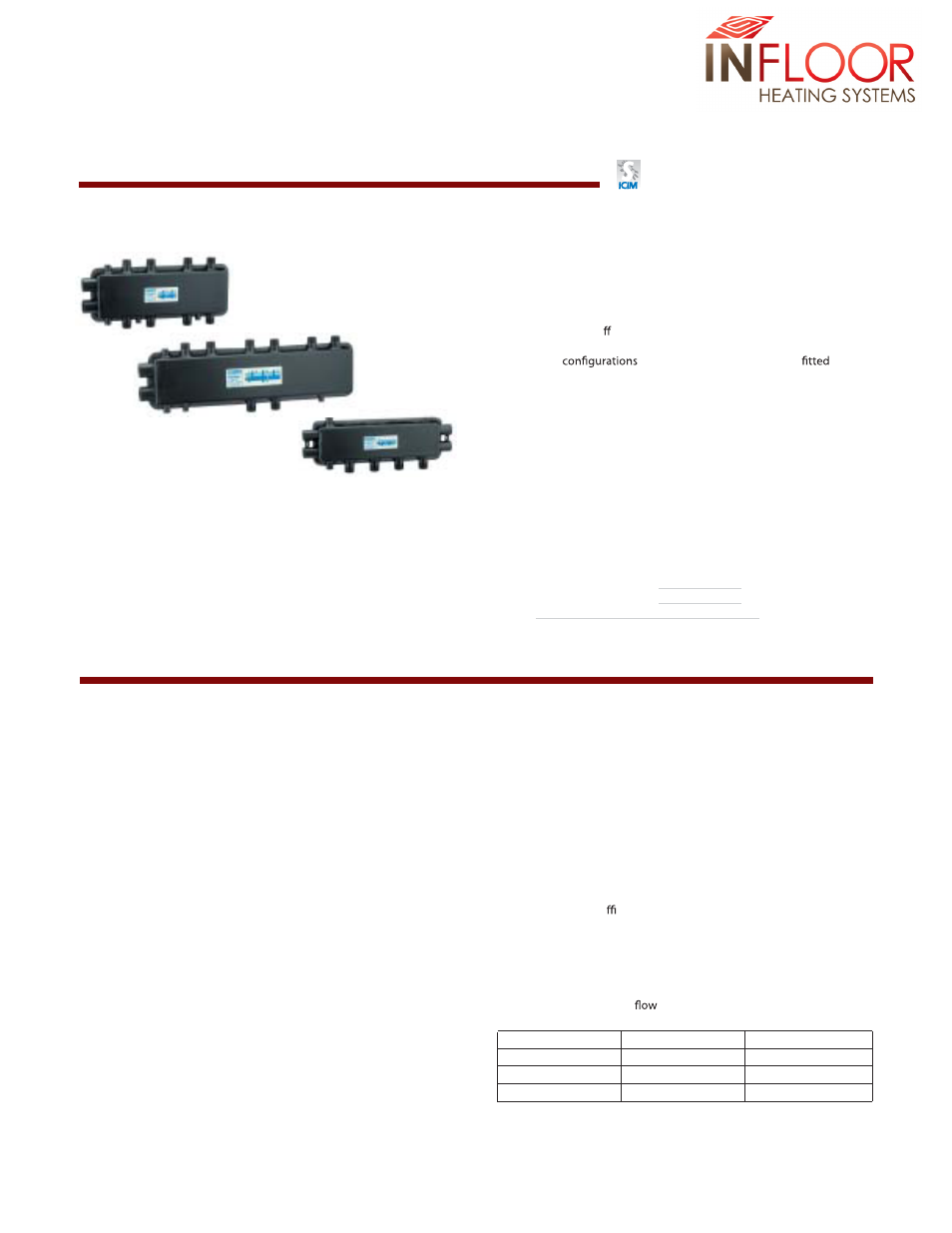
Hydronic separator-manifold
HydroLink™
Function
The Hydrolink, a new device combining a hydronic separator and
distribution manifold, is used in heating and air-conditioning
systems to allow di erent heat adjustments of the various rooms
when there is only one boiler or chiller.
The various
are compact, and can be easily
in
any kind of hydronic circuit, with the advantages of ease of
installation and a saving of useful living space.
Patent application No. MI2001A001270
cert. n° 0003
ISO 9001
Product range
Part # 31091
Exter nal 2+2 separator-manifold. Complete with support brackets and pre-formed insulation
Size 1 1/4”; branches 1”
Part # 31092
External 3+1 separator-manifold. Complete with support brackets and pre-formed insulation
Size 1 1/4”; branches 1”
Part # 31090
Built-in 2+1 separator-manifold. Complete with pre-formed insulation
Size 1”; branches 1”
Technical characteristics
Body
l
e
e
t
s
d
e
t
n
i
a
P
:
y
d
o
B
-
:
l
a
ir
e
t
a
M
Medium:
Water and non-hazardous glycol solutions
%
0
5
:
e
l
o
c
y
l
g
f
o
e
g
a
t
n
e
c
r
e
p
x
a
M
)
r
a
b
6
(
i
s
p
0
9
:
e
r
u
s
s
e
r
p
g
n
i
k
r
o
w
.
x
a
M
Te
)
C
°
0
1
1
÷
0
(
F
°
0
3
2
o
t
2
3
:
e
g
n
a
r
e
r
u
t
a
r
e
p
m
Connections: - main:
3+1 and 2+2:
1 1/4” F NPT
2+1:
1” F NPT
- branches:
3+1 and 2+2:
1” M NPT
2+1 (bottom):
1” M NPT
2+1 (side):
1” F NPT
- air vent valve: 3+1, 2+2 and 2+1: 1/2” F straight
- drain cock: 3+1, 2+2 and 2+1: 1/2” F straight
Center distances: - main:
3+1 and 2+2:
3 1/8” (80 mm)
2+1:
2 3/8” (60 mm)
- branches:
3+1 and 2+2:
3 1/2” (90 mm)
2+1:
3 1/2” (90 mm)
Insulation
Material:
Closed-cell expanded PEX
Thickness:
3/4” (20 mm)
Density:
- inner part:
2 lb/ft
3
(30 kg/m
3
)
- outer part:
3 lb/ft
3
(50 kg/m
3
)
Thermal conductivity: - at 32°F (0°C):
0.26 BTU/in (.038 W/mK)
- at 100°F (40°C): 0.31 BTU/in (.045 W/mK)
Vapor resistance coe cient (DIN 52615):
> 1.300
Temperature range:
32 to 212°F (0÷100°C)
Fire resistance (DIN 4102):
Class 1 (Class B2)
Flow Characteristics
Maximum recommended
rates at connections:
Branches
Primary
Secondary (total)
2+1
9 gpm (2.0 m
3
/h)
22 gpm (5 m
3
/h)
2+2
11 gpm (2.5 m
3
/h)
26 gpm (6 m
3
/h)
3+1
11 gpm (2.5 m
3
/h)
26 gpm (6 m
3
/h)