Infloor Hydrolink 31090-31092 User Manual
Page 4
0,25
0,5
0,75
1,0
1,25
1,5
1,75
2,0
2,25
100
80
60
40
20
-20
0
1
-
5
1
-
-5
0
5
10
15
20
8
CALEFFI
0,25
0,5
0,75
1,0
1,25
1,5
1,75
2,0
2,25
20
CA
LE
FF
I
CA
LE
FF
I
CALEFFI
10
0
8
6
4
2
10
0
8
6
4
2
CALEFFI
10
0
8
6
4
2
10
0
8
6
4
2
10
0
8
6
4
2
10
0
8
6
4
2
CALEFFI
CALEFFI
CA
LE
FF
I
CA
LE
FF
I
CALEFFI
10
0
8
6
4
2
10
0
8
6
4
2
CALEFFI
10
0
8
6
4
2
10
0
8
6
4
2
10
0
8
6
4
2
10
0
8
6
4
2
CALEFFI
CALEFFI
0,25
0,5
0,75
1,0
1,25
1,5
1,75
2,0
2,25
100
80
60
40
20
5
1
-
0
2
-
-10
-5
0
5
10
15
20
9
CALEFFI
0,25
0,5
0,75
1,0
1,25
1,5
1,75
2,0
2,25
20
M S - +
16
18
20
22
24
CALEFFI
M S - +
16
18
20
22
24
CALEFFI
External hydraulic separator-manifold, branches 2+2, for heating and air-conditioning systems. Painted steel body.
Connections to generator 1 1/4” F, centre distance
3 1/8” (80 mm) . Branch connections 1” M, centre distance
3 1/2”
(90 mm) . 1/2” F connections for air vent valve and drain cock. Max. working pressure
90 psi (6 bar) . Temperature
range 32 to 230°F (0÷110°C) . Complete with support brackets.
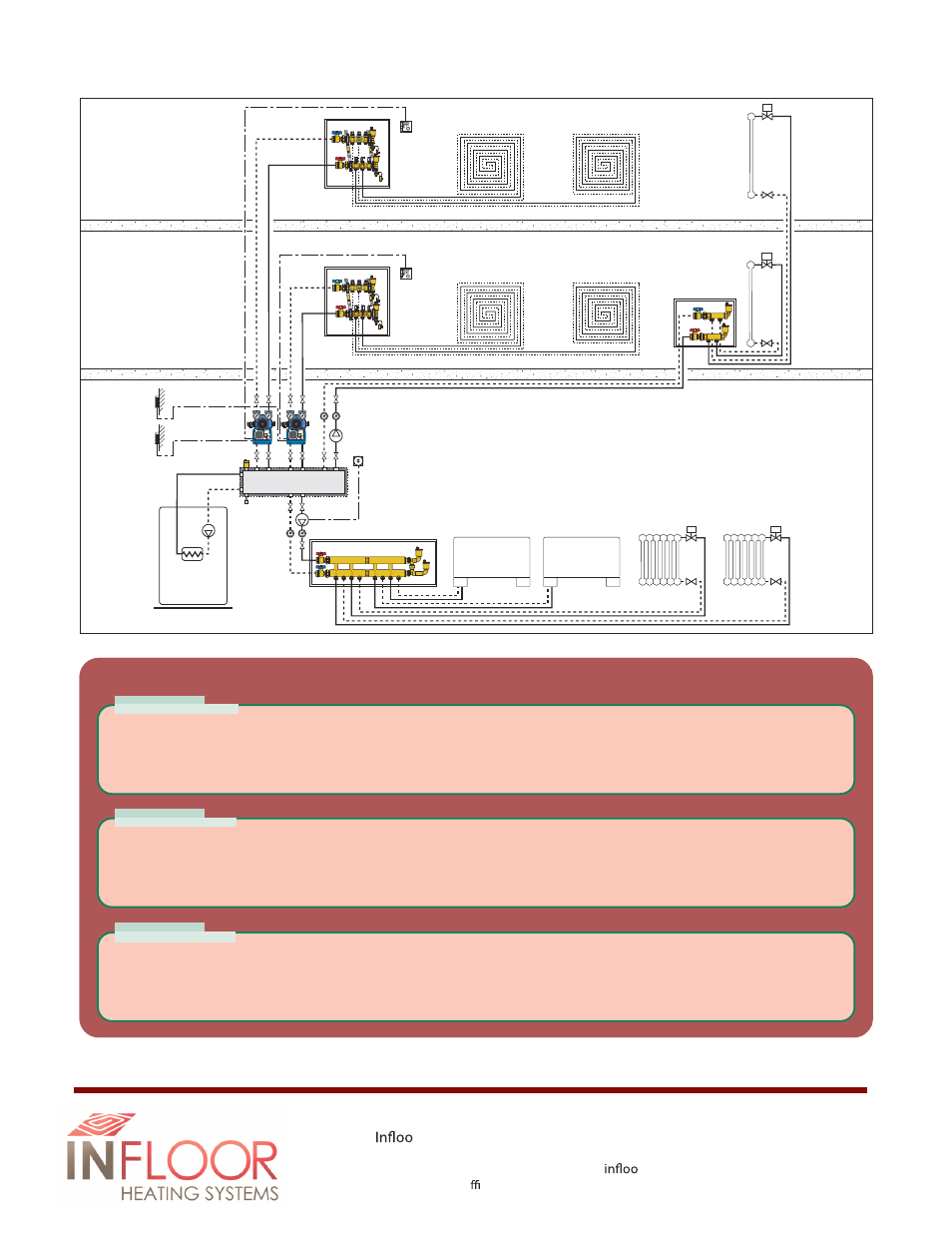
SPECIFICATION SUMMARIES
Part # 31091
External hydraulic separator-manifold, branches 3+1, for heating and air-conditioning systems. Painted steel body.
Connections to generator 1 1/4” F, centre distance
3 1/8” (80 mm) . Branch connections 1” M, centre distance
3 1/2”
(90 mm) . 1/2” F connections for air vent valve and drain cock. Max. working pressure
90 psi (6 bar) . Temperature
range 32 to 230°F (0÷110°C) . Complete with support brackets.
Part # 31092
Built-in hydraulic separator-manifold, branches 2+1, for heating and air-conditioning systems. Painted steel body.
Connections to generator 1” F, centre distance
2 3/8” (60 mm) . Side branch connections 1” M, centre distance
3 1/2” (90 mm) . Head branch connections 1” F, centre distance
2 3/8” (60 mm) . 1/2” F connections for air vent valve
and drain cock. Max. working pressure
90 psi (6 bar) . Temperature range 32 to 230°F (0÷110°C) .
Part # 31090
System with floor
standing boiler and
HydroLink 3+1
We r eserve the right to change our products and their relevant technical data, contained in this publication, at any time and without prior notice.
r Sales & Service
PO Box 4945 / Buena Vista, CO 81211
Tel: 800 .608 .0562 / Fax: 719 .395 .3555 / www.
r.com
© Copyright 2003 Cale North America, Inc.