Repair and test record – Infloor Cable Repair Kit User Manual
Page 4
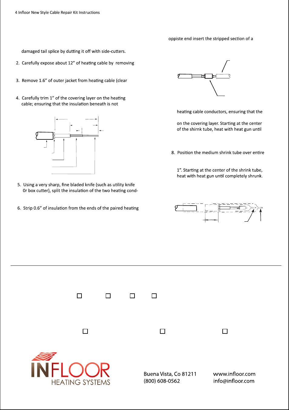
1.6 [41mm]
1.0[26mm]
.6 [15mm]
JACKET
COPPER BRAID
COVERING LAYER
INSULATION
CONDUCTORS
7. Slide 1 small shrink tube over the crimped
shrink tube provides at least 0.5” of overlap
completely shrunk. Before the shrink tube
becomes completely shrunk, use a pair of
pliers to pinch the end closed.
splice area and shrink with the heat gun. The
shrink tube most overlap each splice area by
Before the shrink tube becomes completely
shrunk, use a pair of pliers to pinch the end
closed.
STRANDED
JUMPER
WIRE
CRIMP
CONNECTOR
.5[13mm]
SMALL
HEAT SHRINK
TUBE
MEDIUM
HEAT SHRINK
TUBE
P.O. Box 4945
(719) 395-3555 Fax
HEATING CABLE TAIL SPLICE
1. Carefully expose the original factory splice by removing
any mortar in which the splice is embedded. Remove the
any mortar covering it.
nylon) and ground braid beneath the jacket.
damaged during this step.
TESTING
1. Test the resistance between the primary conductors of the cold lead with an ohmmeter. Record The resistance in the repair & test record.
2. Test the insualtion resistance of the cable between the primary conductor & the ground braid with 500 VDC megger. The restance should
be greater than 20 Megohms. Recored the resistance in the repair and test record.
REPAIR AND TEST RECORD
Repair Address__________________________________________Repair Date _________
Repair Location: Bathroom Kitchen Foyer Others_____________________
Cause of Damage______________________________ Repair Completed by ___________
Original Cable Length _________
Heater Resistance ( ) __________ Ground Continuity ( Yes) Insulation Resistanc (M ) (>20 MO @500 VDC)
NOTICE: REPAIR A DAMAGED CABLE WILL VOID THE ORIGINAL HEATING CABLE WARRANTY.
uctors back to the covering layer.
element conductors. Insert the striped conductors into the
crimp connector (one) on the
jumper wire to act as a filter. Crimp securely.
Cut off excess jumper wire.