Radiant side, Trak installation guide – Infloor Radiant Trak User Manual
Page 2
503 Gregg Dr., Buena Vista, Co 81211
phone 800.608.0562 fax 719. 395.3555
Step 3. Formulas:
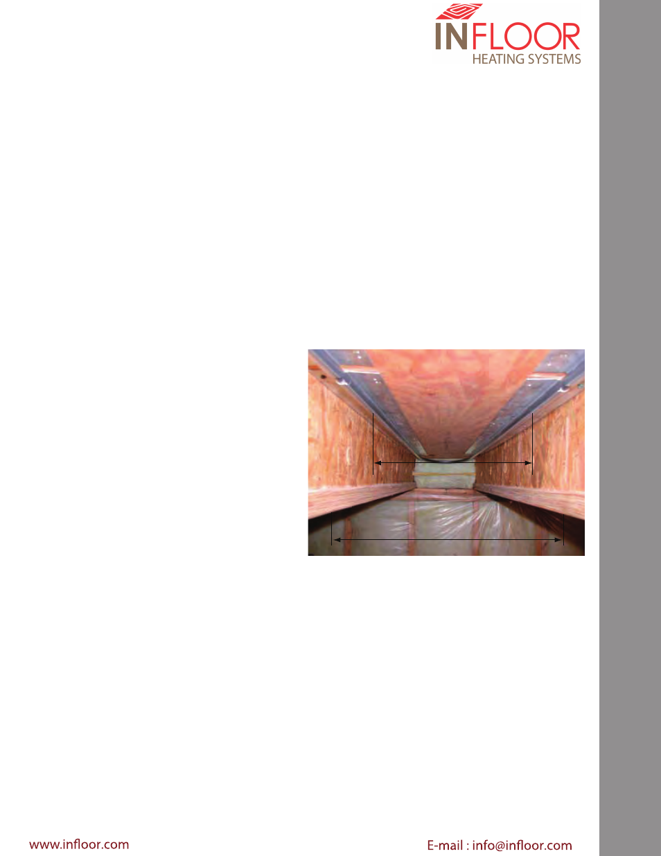
From Below:
Determining the amount of
Radiant Side Track™
Extruded aluminum plates per room
For 24 on center Truss
Multiply three runs per bay - Sq ft. of room x .3895 =
Amount of plates for Staple Up from below.
For 16 on center Floor Joists
Multiply two runs per bay- Sq ft. of room x .3075 =
Amount of plates for Staple Up from below.
For 12 on center Floor Joists
Multiply two runs per bay - Sq ft. of room x .3895 =
Amount of plates for Staple Up from below.
Determining the amount tubing per circuit
24” on center Floor Joists
three runs per bay = Square footage X 2.0 Amount of
heating tube in floor (6” average on center tube spacing)
16” on center Floor Joists
two runs per bay = Square footage X 1.4 = Amount of heating
tube in floor (8” average on center tube spacing)
12” on center Floor Joists
two runs per bay = Square footage X 2.0 Amount of heating
tube in floor (6” average on center tube spacing)
Maximum developed circuit lengths:
3/8”
” = not to exceed
200 ft
1/2” = not to exceed
300 ft
Design Notes:
Radiant Side Trak™ is sold for use in dry method radiant
heat installations; where plastic heating pipes are secured
into an extruded aluminum plate and fastened to the
underside of a subfloor.
This is known as the staple up method.
Radiant ceiling heat and wall heating are other methods of
which
Radiant Side Trak™ can be utilized
Proper installations:
Step 1.
Determine the your heating requirements
The first step in your radiant heating system design is
to determine the individual area heating requirements.
Conventional heat loss calculations should not be utilized
(e.g. IBR method) for a radiant heating design.
The preferred heatloss method is Manual J or ASHRAE or
equivalent.
The proper R or U values and air changes per hour should
be selected in these calculations. Once this process has
been completed then the proper tube spacing and tubing
deployment patterns can be recommended.
Step 2.
Required performance
After your heatloss calculation has been performed, you
can now derive your heatloss per square foot in each
respective area.
Check the attached performance charts to make sure
you’re per square foot heatloss does not exceed maximum
allowable performance characteristics. Your radiant heat
system should never be designed to exceed 35 BTU’s per
square foot of performance, as excessive floor surface
temperature (85F @ 68 F room temperature) can damage
finish flooring materials-voiding manufacturers’ warranties.
Furthermore, excessive floor surface temperature will
cause foot sweating and athletes foot.
Studies have revealed that high floor surface temperature
can cause early onset of varicose veins and could be
detrimental to ones cardio vascular system. If your
heatloss exceeds 35 BTU’s per square foot, then provide
supplemental heat for the respective areas or select
another style heat source.
Radiant Side
Trak Installation Guide
8”
16”