Gpi input pins gpi output pins – JLCooper eBOX User Manual
Page 38
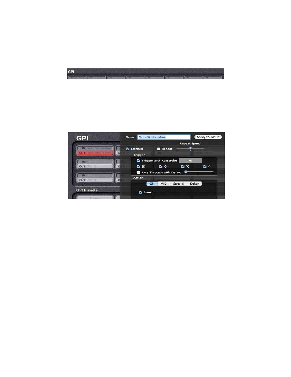
GPI Input Pins
The top group of buttons each represents Individual GPI pins.
There are three rows of input pins and three rows of output pins.
For the Input pins, you can program what happens when an
individual input pin is changed by some external hardware.
Currently the GPI Input pins can generate MIDI Messages and
Delays.
GPI Output Pins
Each GPI Output pin button can change the state of its pin, without
affecting the other pins. In the GPI tab, you can create a GPI
action that closes the contact when the button is pressed and opens
it when released. If you click on the Invert check box, then it
opens the contact on the button press and closes it on release.
Currently the Special Tab is not implemented. But even without it
you have the ability to do something like turn on a contact then
delay up to 2 seconds then turn it off again, plus send a MIDI
message to an application, and this can be triggered by a keystroke
that also does something useful in another program, like Pro Tools.
38