Installation of mig system, Accessories corresponding to wire diameter – Kemppi Promig 540R User Manual
Page 10
10 – Promig 540R, Promig 120R/0425
©
KEMPPI
OY
Promig 540R, Promig 120R/0423 – 11
©
KEMPPI
OY
20
21 23
24
21
22
25
22
25
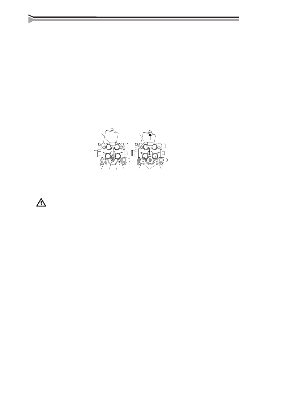
– Open tightening lever (20). Remove lower feed rolls (21). Release screw (23) and its washer.
Remove gear wheel D28 (24) from motor shaft.
– Loosen screws (25) (3 pcs) by one twist. Mount D40 gear wheel onto motor shaft. Screw the
screw (23) with its washer back.
– Put feed rolls (21) back on their shafts.
– Lift motor so that tooth gap between gear wheel and both lower feed rolls is approx. 0,2 mm.
– Tighten screws (25). Check gear teeth gaps, if necessary put the motor into a better position.
Screw on mounting screws of feed rolls (22).
Too small a clearance between drive wheel and feed rolls will overload the
motor. Too large a clearance causes rapid wearing of feed rolls’ drive wheel.
3. INSTALLATION OF MIG SYSTEM
3.1. ACCESSORIES CORRESPONDING TO WIRE DIAMETER
PROMIG wire feed rolls are available with plain groove, knurled groove and with U groove.
Feed rolls with plain groove:
Universal feed roll for welding of all kinds of wires.
Feed rolls with knurled groove:
Special feed roll for cored wires and steel wires.
Feed rolls with U groove:
Special feed roll for aluminium wires.
PROMIG wire feed rolls have two grooves. Correct wire groove is selected by moving selecting
washer from over to underneath the feed rolls. Move also drive wheel with the black plastic
washer.
Feed rolls and wire guide tubes of wire feed unit have colour codes to make identification easier.