Mounting of mig gun, Automatic wire feed to gun, Adjustment of pressure – Kemppi Promig 540R User Manual
Page 11
10 – Promig 540R, Promig 120R/0425
©
KEMPPI
OY
Promig 540R, Promig 120R/0423 – 11
©
KEMPPI
OY
3.2. MOUNTING OF MIG GUN
To ensure trouble-free welding, check in welding gun operating instructions that wire liner and
contact tip are correct for wire feed diameter and wire type. Too tight a wire liner might cause
disturbances in wire feed, and motor overload (this is also a symptom of liner blockage).
Ensure that the welding gun connector is tight.
When you are using liquid-cooled gun, mount water hoses according to the diagram.
Error signal lamp of PROMIG 540R indicates overloading of wire feed motor. Operation of
signal lamp is as follows (also see error codes):
Wire feed motor is slightly overloaded e.g. due to a blocked gun. At a predetermined load the
error signal lamp starts to blink.
If the load is too great the system will shut down (wire feed) and the display panel will indicate
Err 9.
Error code 9, followed by blinking signal lamp is cleared by next start if error condition is no
longer present or motor is not overheated any more.
3.3. AUTOMATIC WIRE FEED TO GUN
Automatic wire feed in PROMIG wire feed units makes changing of wire reel more rapid. When
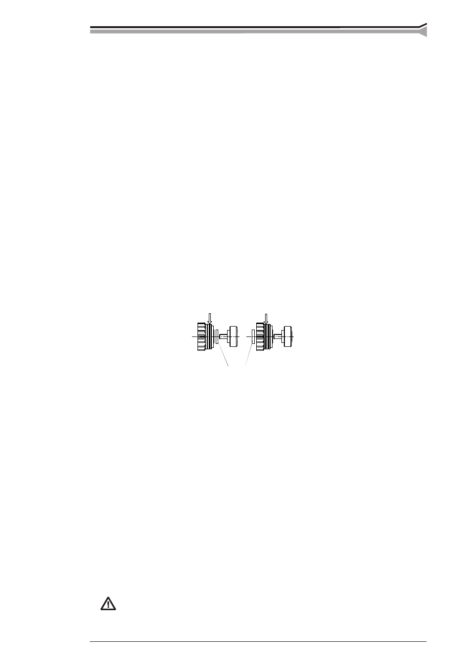
changing the reel, feed rolls need not be released as the wire will pass directly through.
Groove selecting washer
– Make sure that groove of feed roll matches the diameter of welding wire used. Feed roll
groove is selected by moving the groove selecting washer from top to bottom or vice versa.
– Straighten the wire at a length of about 20 cm and see that its end has no sharp edges (file
off if necessary). A sharp edge may damage the wire guide tube and contact tip of welding
gun.
Automatic feed may sometimes fail with thin wires (Fe, Fc, Ss: 0,6...0,8 mm, Al: 0,8...1,0 mm).
Then you might have to open feed rolls and feed wire manually through feed rolls.
– Feed wire through wire cone until it touches the feed rolls. Do not release pressure of feed
rolls!
– Press wire inch switch and feed wire until wire goes through both sets of rolls.
– Keep inch switch pressed until wire has come through contact tip.
3.4. ADJUSTMENT OF PRESSURE
Adjust feed roll pressure with the control screw (20) so that some resistance may be applied to
the wire without slipping at the feed rolls.
Excessive pressure causes flattening of filler wire and damage to the coating. It
also causes undue wear of feed rolls as well as friction.