Rear panel, 10 english, B fm antenna terminal (75 ohms) – Marantz SR-12S1N User Manual
Page 13: Am antenna and ground terminals, N multiroom outputs (audio l&r, video), M monitor out, Component video input/output, X preamp outputs (l, r, sl, sr, sbl, sbr, c), C subwoofer output, V main amplifier inputs
10
ENGLISH
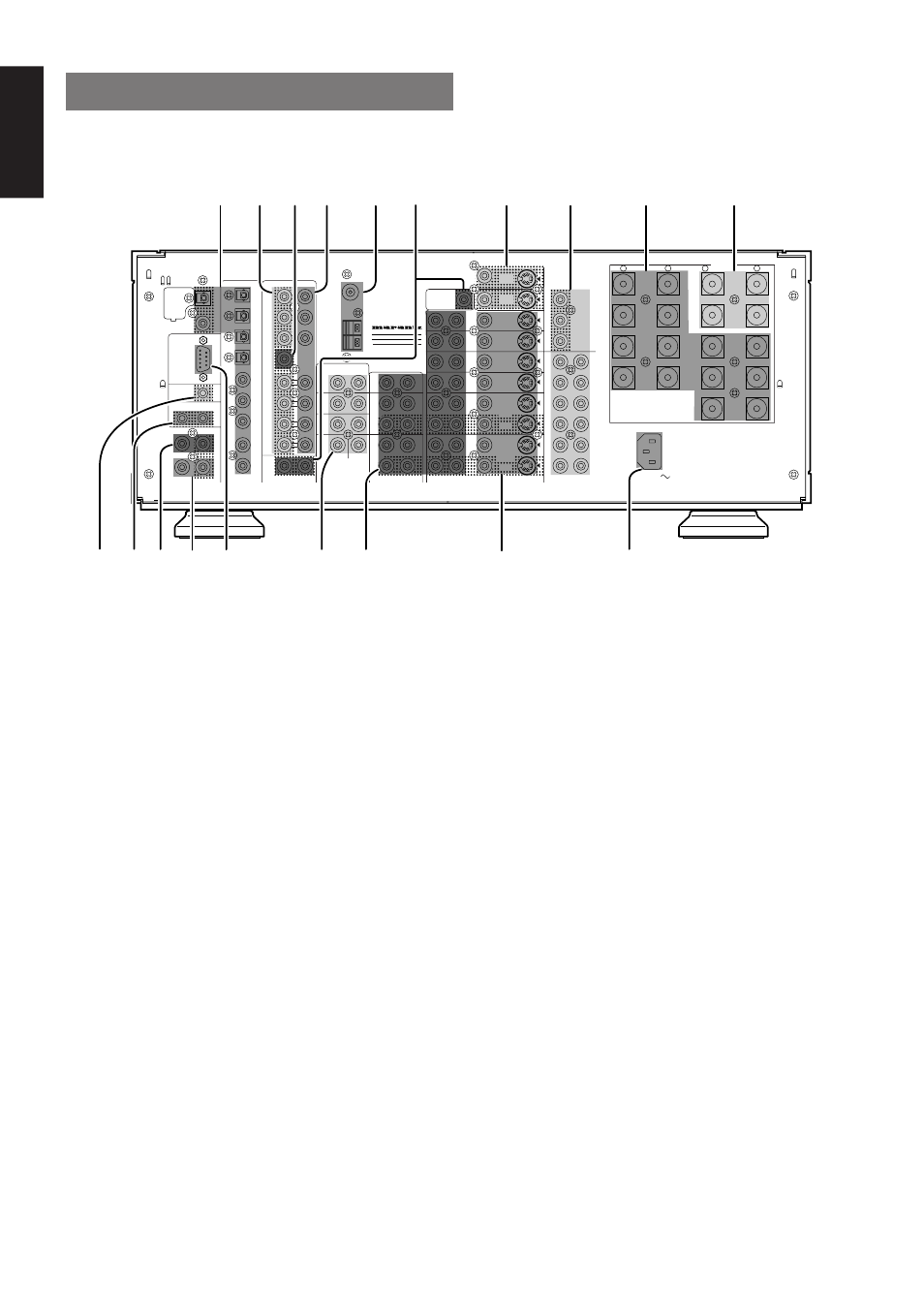
REAR PANEL
b FM antenna terminal (75 ohms)
Connect an external FM antenna with a coaxial cable, or a cable
network FM source.
AM antenna and ground terminals
Connect the supplied AM loop antenna. Use the terminals marked
“AM” and “GND”. The supplied AM loop antenna will provide good
AM reception in most areas. Position the loop antenna until you hear
the best
n Multiroom Outputs (Audio L&R, Video)
These are the audio and video output jacks for the remote zone (Multi
Room).
Connect these jacks to the optional audio power amplifiers or video
display devices to view and listen to the source selected by the
mulitroom system in a remote room.
m MONITOR OUT
There are 2 monitor outputs and each one includes both composite
video and S-video configurations. When connecting two video
monitors or televisions, be aware that the OSD interface can be used
with both MONITOR OUT.
, COMPONENT VIDEO INPUT/OUTPUT
If your DVD player or other device has component video connectors,
be sure to connect them to these component video connectors on the
SR-12S1. The SR-12S1 has four component video input connectors
to obtain the color information (Y, C
B
, C
R
) directly from the recorded
DVD signal or other video component and one component video
output connector to output it directly into the matrix decoder of the
display device.
By sending the pure DVD component video signal directly, the DVD
signal forgoes the extra processing that normally would degrade the
image. The result is vastly increased image quality, with incredibly
lifelike colors and crisp detail.
Notes:
• This component video output is available to OSD menu system.
z DIGITAL INPUT (Dig.1 - 9) / OUTPUT
(coaxial, optical)
These are the digital audio inputs and outputs. There are 5 digital
inputs with coaxial jacks, 4 with optical jacks.
The inputs accept digital audio signals from a compact disc, LD, DVD,
or other digital source component.
For digital output, there is 1 coaxial output and 1 optical output.
The digital outputs can be connected to MD recorders, CD recorders,
DAT decks, or other similar components.
x Preamp Outputs (L, R, SL, SR, SBL,
SBR, C)
When the jumper plugs that link the Amplifier Inputs with these outputs
are removed, these jacks may be connected to an external power
amplifier.
c Subwoofer Output
Connect this jack to the line level input of a powered subwoofer. If an
external subwoofer amplifier is used, connect this jack to the
subwoofer amplifier input. If you are using two subwoofers, either
powered or with a 2 channel subwoofer amplifier, connect a “Y”
connector to the subwoofer output jack and run one cable from it to
each subwoofer amplifier.
v Main Amplifier Inputs
When the jumper plugs that link the Preamp Outputs with these inputs
are removed, these jacks may be used to connect an external source
to the internal amplifiers.
Notes:
• When connecting a equipment, remove the attached jumper
plugs and store them carefully so as not to lose them.
• Only remove the jumper plugs when required. After you finish
using an Main Amp Input jack, replace the jumper plug.
RC
MULTI
OUT
EXT. IR
OPT
COAX
DIGITAL-OUT
AC IN
MODEL NO.SR-12S1
6-8 OHMS
SPEAKER SYSTEMS
OUT
IN
SBR
DVD-R
VCR2/
SBL
1
ROOM
MULTI
ROOM
MULTI
R
L
SW
RIGHT
LEFT
DC OUT 2
OUT
MULTI VIDEO
ANTENNA
BACK
SURR.
CENTER
C
SR
SL
R
L
OUT
MULTI
RS232C
DC OUT 1
RIGHT
LEFT
SURR.
CENTER
BACK
BACK
SURR.
RIGHT
LEFT
FRONT
LEFT
–
+
SURR.
FRONT
SURR.
RIGHT
DIGITAL-IN
9
8
7
6
5
4
3
2
FRONT
(AUX 2)
MAIN IN
SURR.
7.1CH-INPUT
R
AM
GND
LD
OUT
OUT
S-VIDEO
VIDEO
VCR1
AUDIO
IN
MONI.
1
L
/MD
CD-R
IN
OUT
CD
IN
DVD
L
TAPE
OUT
PRE OUT
IN
R
TV
MONI.
2
L
R
DSS
–
+
RC-5
GND
VCR1
IN
DVD
IN
DSS
IN
MONITOR
OUT
CR
CB
Y
COMPONENT VIDEO
VCR2 /
DVD - R
IN
CR
CB
Y
CR
CB
Y
SUB WOOFER
c v b n
x
z
m
.
Ú0
,
Ú5
Ú4 Ú3
Ú2
Ú1
Ú6
Ú7
Ú8
Ú9