25 english, Connecting the audio components, Caution – Marantz SR-12S1N User Manual
Page 28
25
ENGLISH
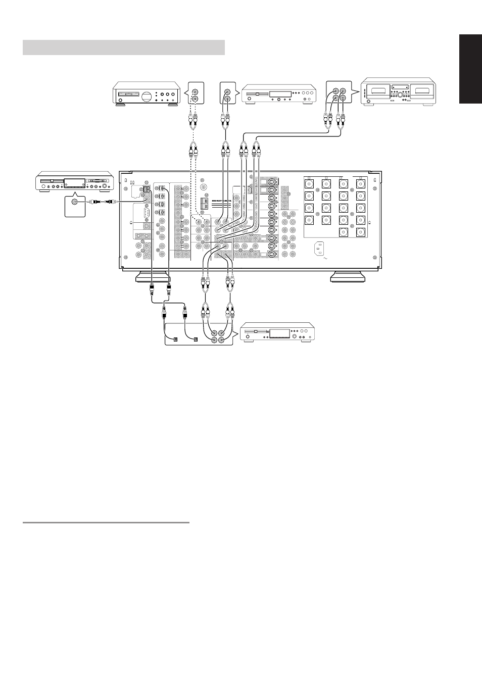
CONNECTING THE AUDIO COMPONENTS
The output audio signal from the TAPE OUT jack and the CD-R/MD
OUT jack is the sound source currently selected.
Caution:
• Do not connect this unit and other components to mains power
until all connections between components have been
completed.
Notes:
• Insert all plugs and connectors securely. Incomplete
connections may make noise.
• Be sure to connect the left and right channels properly.
Red connectors are for the R (right) channel, and white
connectors are for the L (left) channel.
• Be sure to connect input and output properly.
• Refer to the instructions for each component that is connected
with this unit.
• Do not bind audio/video connection cables with power cords
and speaker cables will result in generating hum or other noise.
CONNECTING DIGITAL AUDIO COMPONENTS
• There are 9 digital inputs, 5 coaxial jacks and 4 optical jacks, on the
rear panel. You can use these jacks to input PCM, Dolby Digital and
DTS bitstream signals from a CD, DVD, or other digital source
components.
• There are one digital output with coaxial jack and one with optical
jack on the rear panel. These jacks can be connected to CD
recorder, MD deck.
• Setup the digital audio format of DVD player, or other digital source
component. Refer to the instructions for each component to be
connected to digital input jacks.
• Use fiber optical cables (optical) for DIG-1, 2, 3, 4 input jacks. Use
75 ohms coaxial cables (for digital audio or video) for DIG-5, 6, 7, 8,
9 input jacks.
• You can designate the input for each digital input/output jacks
according to your component. See page 32.
Notes:
• There is no Dolby Digital RF input jack. Please use an external
RF demodulator Dolby Digital decoder when connecting the
Dolby Digital RF output jack of the video disc player to the
digital input jack.
• The digital signal jacks on this unit conform to the EIA
standard. If you use a cable that does not conform to this
standard, this unit may not function properly.
• Each type of audio jack works independently. Signals input
through the digital and analog jacks are output through the
corresponding digital and analog jacks, respectively.
CD RECORDER
MD PLAYER
SACD PLAYER
CD PLAYER
TAPE DECK
RC
MULTI
OUT
EXT. IR
OPT
COAX
DIGITAL-OUT
AC IN
MODEL NO.SR-12S1
6-8 OHMS
SPEAKER SYSTEMS
OUT
IN
SBR
DVD-R
VCR2/
SBL
1
ROOM
MULTI
ROOM
MULTI
R
L
SW
RIGHT
LEFT
DC OUT 2
OUT
MULTI VIDEO
ANTENNA
BACK
SURR.
CENTER
C
SR
SL
R
L
OUT
MULTI
RS232C
DC OUT 1
RIGHT
LEFT
SURR.
CENTER
BACK
BACK
SURR.
RIGHT
LEFT
FRONT
LEFT
–
+
SURR.
FRONT
SURR.
RIGHT
DIGITAL-IN
9
8
7
6
5
4
3
2
MAIN IN
SURR.
R
AM
GND
LD
OUT
OUT
S-VIDEO
VIDEO
VCR1
AUDIO
IN
MONI.
1
L
/MD
CD-R
IN
OUT
CD
IN
DVD
L
TAPE
OUT
PRE OUT
IN
R
TV
MONI.
2
L
R
DSS
–
+
RC-5
GND
VCR1
IN
DVD
IN
DSS
IN
MONITOR
OUT
CR
CB
Y
COMPONENT VIDEO
VCR2 /
DVD - R
IN
CR
CB
Y
CR
CB
Y
FRONT
(AUX 2)
7.1CH-INPUT
SUB WOOFER
DIGITAL
INPUT
OUT IN
L
R
L
R
DIGITAL
OUTPUT
DIGITAL
INPUT
OUT IN
L
R
L
R
OUT
L
R
OUT
L
R
L R
L R
L R
R L
R L
R L
L R
R L
R L
R L
R L
L R