30 english, Connecting for the multi room, Connecting remote control jacks – Marantz SR-12S1N User Manual
Page 33: External internal
30
ENGLISH
RC
MULTI
OUT
EXT. IR
OPT
COAX
DIGITAL-OUT
AC IN
MODEL NO.SR-12S1
6-8 OHMS
SPEAKER SYSTEMS
OUT
IN
SBR
DVD-R
VCR2/
SBL
1
ROOM
MULTI
ROOM
MULTI
R
L
SW
RIGHT
LEFT
DC OUT 2
OUT
MULTI VIDEO
ANTENNA
BACK
SURR.
CENTER
C
SR
SL
R
L
OUT
MULTI
RS232C
DC OUT 1
RIGHT
LEFT
SURR.
CENTER
BACK
BACK
SURR.
RIGHT
LEFT
FRONT
LEFT
–
+
SURR.
FRONT
SURR.
RIGHT
DIGITAL-IN
9
8
7
6
5
4
3
2
MAIN IN
SURR.
R
AM
GND
LD
OUT
OUT
S-VIDEO
VIDEO
VCR1
AUDIO
IN
MONI.
1
L
/MD
CD-R
IN
OUT
CD
IN
DVD
L
TAPE
OUT
PRE OUT
IN
R
TV
MONI.
2
L
R
DSS
–
+
RC-5
GND
VCR1
IN
DVD
IN
DSS
IN
MONITOR
OUT
CR
CB
Y
COMPONENT VIDEO
VCR2 /
DVD - R
IN
CR
CB
Y
CR
CB
Y
FRONT
(AUX 2)
7.1CH-INPUT
SUB WOOFER
REMOTE CONTROL
IN
OUT
REMOTE CONTROL
IN
OUT
REMOTE CONTROL
IN
OUT
EXTERNAL INTERNAL
EXTERNAL INTERNAL
EXTERNAL INTERNAL
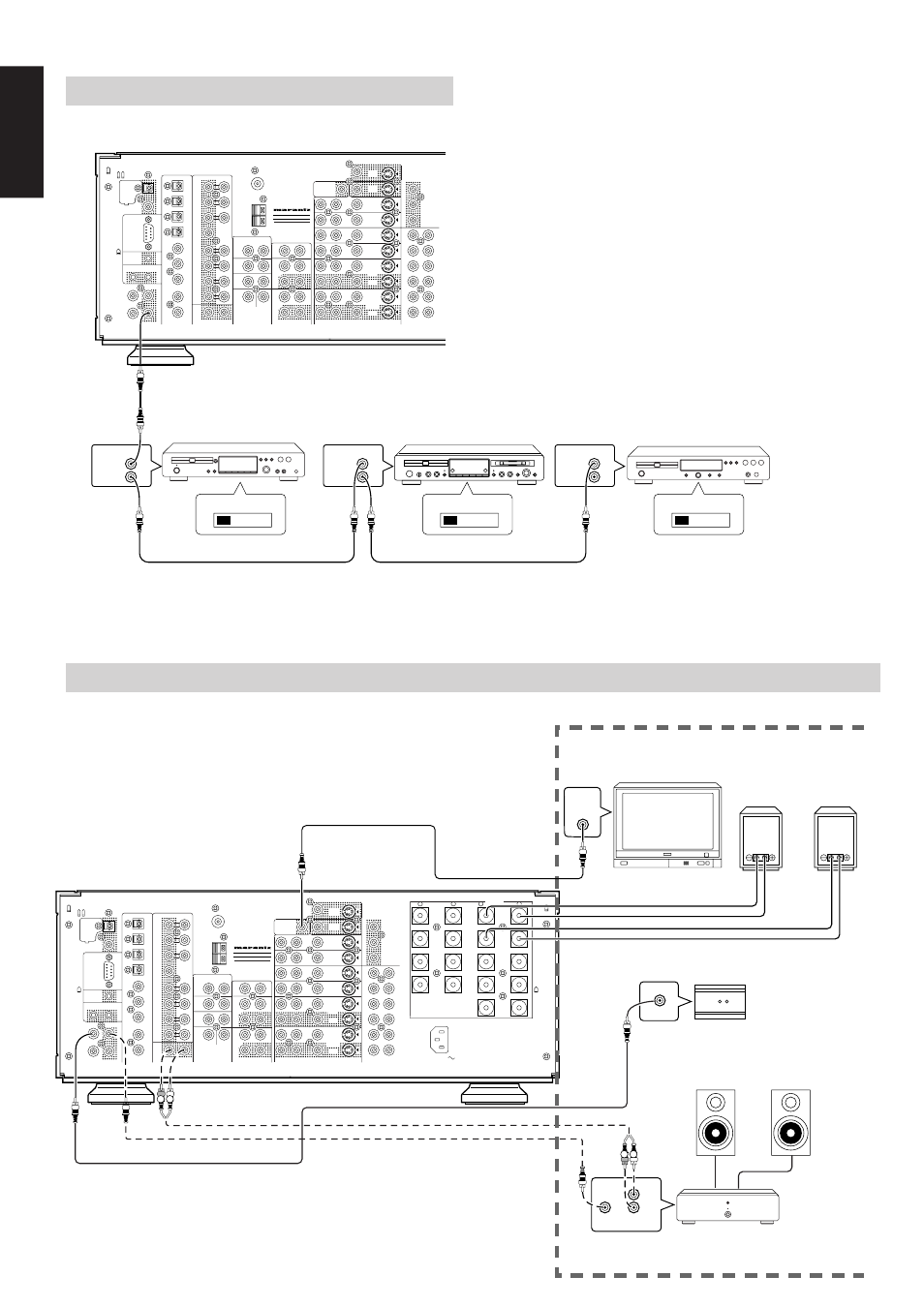
CONNECTING FOR THE MULTI ROOM
MONITOR
MULTI ROOM
RIGHT
I
IR RECEIVER
MULTI ROOM
LEFT
MULTI ROOM
RIGHT
MAIN AMP
(FOR
MULTIROOM)
CD PLAYER
MD PLAYER
CD RECORDER
CONNECTING REMOTE CONTROL JACKS
You can control other Marantz products through this unit with the
remote controller by connecting REMOTE CONTROL terminals on
each unit.
The signal transmitted from the remote controller is received by the
remote sensor on this unit then the signal is sent to the connected
device through this terminal. Therefore you need to aim the remote
signal only to the unit. Also, if a Marantz power amplifier (some models
excluded) is connected with this terminal, the power amplifier’s power
switch is synchronized with this unit’s power switch.
Set the REMOTE CONTROL SWITCH on the units other than this unit
to EXT. (EXTERNAL) for this feature.
MULTI ROOM
LEFT
RC
MULTI
OUT
EXT. IR
OPT
COAX
DIGITAL-OUT
AC IN
MODEL NO.SR-12S1
6-8 OHMS
SPEAKER SYSTEMS
OUT
IN
SBR
DVD-R
VCR2/
SBL
1
ROOM
MULTI
ROOM
MULTI
R
L
SW
RIGHT
LEFT
DC OUT 2
OUT
MULTI VIDEO
ANTENNA
BACK
SURR.
CENTER
C
SR
SL
R
L
OUT
MULTI
RS232C
DC OUT 1
RIGHT
LEFT
SURR.
CENTER
BACK
BACK
SURR.
RIGHT
LEFT
FRONT
LEFT
–
+
SURR.
FRONT
SURR.
RIGHT
DIGITAL-IN
9
8
7
6
5
4
3
2
MAIN IN
SURR.
R
AM
GND
LD
OUT
OUT
S-VIDEO
VIDEO
VCR1
AUDIO
IN
MONI.
1
L
/MD
CD-R
IN
OUT
CD
IN
DVD
L
TAPE
OUT
PRE OUT
IN
R
TV
MONI.
2
L
R
DSS
–
+
RC-5
GND
VCR1
IN
DVD
IN
DSS
IN
MONITOR
OUT
CR
CB
Y
COMPONENT VIDEO
VCR2 /
DVD - R
IN
CR
CB
Y
CR
CB
Y
FRONT
(AUX 2)
7.1CH-INPUT
SUB WOOFER
L
R
FRONT
RC IN
R L
R L
RC OUT
IN
VIDEO