Parts, tools, materials – Maytag MMV5207ACQ Installation User Manual
Page 6
Parts, Tools, Materials
6
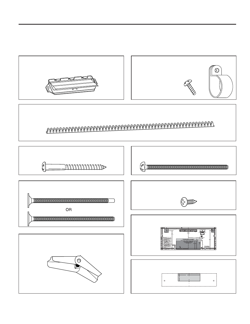
THE FOLLOWING PARTS ARE SUPPLIED WITH THE OVEN:
NOTE: Depending on your ventilation requirements, you may not use all of these parts.
Damper/duct connector
(for roof venting or wall venting installation)
Not Actual Size (2 pieces must be assembled as
shown)
One power cord clamp and
One dark-colored mounting screw
(to hold the power cord)
Actual Size
Two tapping screws - Actual Size
(for attaching the damper duct connector)
One power cord clamp bushing - Actual Size (for the cord hole in a metal upper cabinet)
NOTE: You need to install at least two lag screws into a 2" x 4" stud and four anchor bolts into the wall.
and the mounting area must meet the 150 lbs. weight requirement.
Four 1/4" x 2" lag screws - Actual Size
(for wall stud holes)
Four 1/4" x 3" toggle bolts - Actual Size
(for drywall holes)
Two 1/4" x 3" bolts - Actual Size
(for securing to the upper cabinet)
Four spring toggle heads - Actual Size
(for the toggle bolts)
One upper cabinet template- Not Actual Size
One rear wall template- Not Actual Size
(3 pieces mounting plate only)
12
4
REAR WALL TEMPLATE
CAUTION — IF EXHAUST ADAPTOR IS POSITIONED OUTSIDE
RECOMMENDED DIMENSION, GREASE LADEN AIR WILL
DISCHARGE INTO HOUSE STRUCTURE.
LINE UP WITH
PREVIOUSLY
DRILLED HOLE
B.
LINE UP WITH
PREVIOUSLY
DRILLED HOLE
A.
Printed in Korea
NOTE: IT IS VERY IMPORTANT TO
READ AND FOLLOW THE DIRECTIONS
IN THE INSTALLATION INSTRUCTIONS
BEFORE PROCEEDING WITH THIS
REAR WALL TEMPLATE.
This template is for locating the wall venting
cutout. Do not use this template for roof
or room venting.
1. Place the template flat against the rear
wall, aligning circles A and B with the
corresponding holes previously drilled in the
rear wall for holes A and B of the wall plate.
2. With the template aligned to the holes, tape the
template to the rear wall.
3. Use a saber or keyhole saw to cut out the shaded
area F through the rear wall.
4. Remove the template from the rear wall.
5.
RETURN TO AND PROCEED WITH THE
INSTALLATION INSTRUCTIONS.
1/4
P/N. 4922W5A060A
F. CUT OUT FOR WALL
VENTED ONLY
CUT HOLE THROUGH REAR WALL FOR EXHAUST ADAPTOR