Field wiring, signal termination and conditioning, The red stripe identifies pin # 1 – Measurement Computing PCI-CTR05 User Manual
Page 11
Advertising
PCI-CTR05 User's Guide
Installing the PCI-CTR05
11
20
1
37
19
20
1
37
19
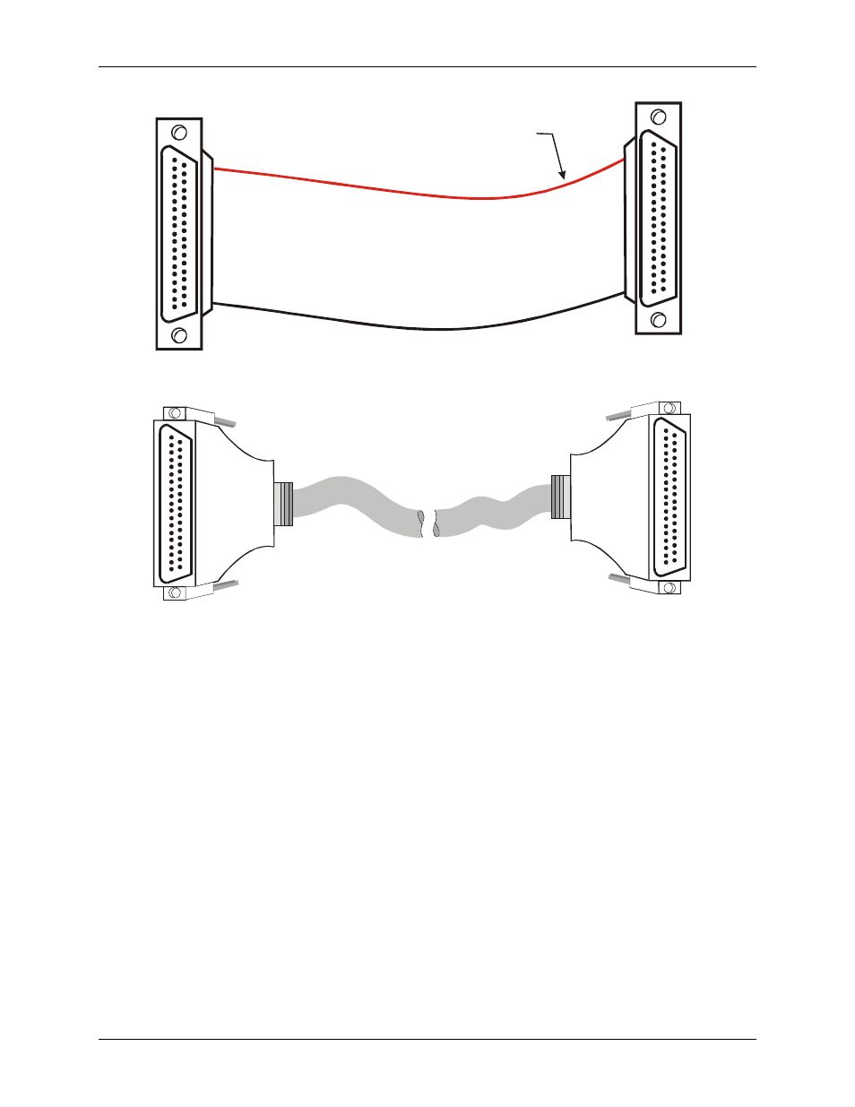
The red stripe
identifies pin # 1
Figure 3. C37FF-x cable
20
1
37
19
20
1
37
19
Figure 4. C37FFS-x cable
Field wiring, signal termination and conditioning
You can use the following MCC screw terminal boards with the PCI-CTR05 board using the C37FF-x or
C37FFS-x cable.
SCB37 — 37-conductor, shielded signal connection/screw terminal box that provides two independent 37-
pin connections.
CIO-MINI37 — 4 x 4, 37-pin screw terminal board.
CIO-MINI37-VERT — 37-pin screw terminal accessory with vertical 37-pin male D connector.
CIO-TERMINAL — 16 X 4 universal screw terminal board with on-board prototype area and circuitry.
Details on these products are available on our web site.
Advertising