Specifications, Digital input / output, Interrupt – Measurement Computing PCI-CTR05 User Manual
Page 13: Counter
13
Chapter 3
Specifications
All specifications are subject to change without notice.
Typical for 25 °C unless otherwise specified.
Specifications in italic text are guaranteed by design.
Digital input / output
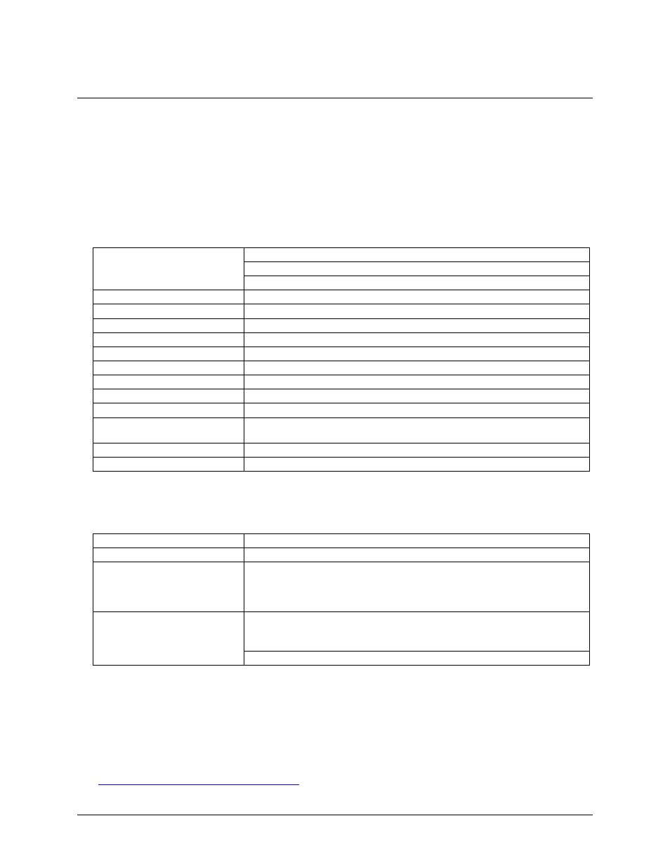
Table 1. Digital I/O specifications
Digital type
Discrete, 5 V/TTL compatible
Output: 74ACT273
Input:
74LS373
Number of I/O
8 input, 8 output
Configuration
1 bank of 8 as output, 1 bank of 8 as strobed input
Input high voltage
2.0 V min, 7.0 V absolute max
Input low voltage
0.8 V max, –0.5 V absolute min
Output high voltage
3.94 V min @ -24 mA (Vcc = 4.5 V)
Output low voltage
0.36 V max @ 24 mA (Vcc = 4.5 V)
Data transfer
Programmed I/O
Power-up / reset state
Digital outputs reset to TTL low
Digital input strobe
Active low latch enable input, internally pulled high through 10 KΩ resistor
Digital input strobe pulse width
high/low
15 ns min
Data setup to digital input strobe
5 ns min
Data hold from digital input strobe
20 ns min
Interrupt
Table 2. Interrupt specifications
Number of user interrupts
1
PCI interrupt
PCI INTA# - mapped to IRQn via PCI BIOS at boot-time
Interrupt enables
External: IRQ ENABLE, active low, disabled by default through internal resistor to
TTL high and programmable through PCI9030-AA60PI.
0 = disabled
1 = enabled (default)
Interrupt sources
External: IRQ IN, polarity programmable through PCI9030-AA60PI.
1 = active high
0 = active low (default)
IRQ IN maps to PLX 9030 LINT1.
Counter
Refer to the CTS9513-2 data sheet for complete 9513 specifications and operating modes. The SAVE command
for the CTS9513 device does not behave predictably when using clocks which are not synchronous with the
logic timing. The CTS9513-2 data sheet is available on our web site at
www.mccdaq.com/PDFs/Manuals/9513A.pdf
.