Measurement Computing PCI-CTR05 User Manual
Page 14
PCI-CTR05 User's Guide
Specifications
14
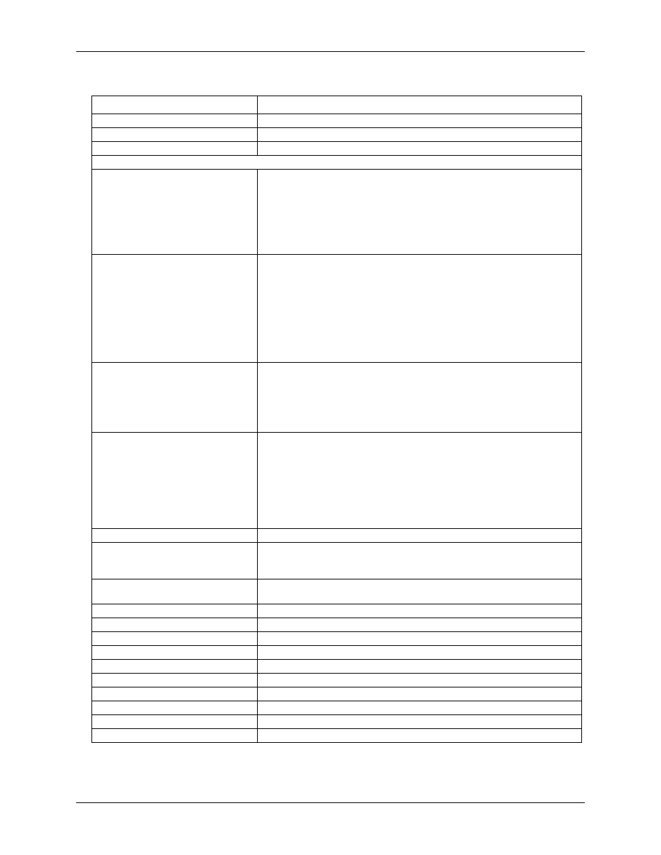
Table 3. Counter specifications
Parameter
Conditions
Counter type
9513
Configuration
One 9513 device. Five up/down counters, 16-bits each.
Compatibility
5V/TTL
The 9513 device is programmable for:
Clock source
Software selectable:
External:
Counter 1-5 clock inputs
Counter 1-5 gate inputs
Internal:
Terminal count of previous counter
X2 clock frequency scaler
Gate:
Software selectable source:
External (default logic high):
Active high or low level or edge, counter 1 – 5 gate input
Active high level previous gate or next gate
All external gate signals (CTRxGATE) individually pulled up through
10 KΩ resistors to +5 V.
Internal:
Active high previous counter terminal count
No gating.
Output:
Software selectable:
Always low
High pulse on terminal count
Low pulse on terminal count
Toggle on terminal count
Inactive, high impedance at user connector counter # output.
Osc Out
Software selectable source:
Counter # input
Gate # input
Prescaled clock source (X2 clock frequency scaler)
Software selectable divider:
Division by 1-16
Software selectable enable:
On or low impedance to ground.
Clock input frequency
6.8 MHz max (145 ns min period)
X2 clock input sources
Software selectable:
1.0 MHz (10 MHz Xtal divided by 10)
5.0 MHz (10 MHz Xtal divided by 2)
X2 clock frequency scaler
BCD scaling (X2 divided by 10, 100, 1000 or 10000) or binary scaling
(X2 divided by 16, 256, 4096 or 65536)
High pulse width (clock input)
70 ns min
Low pulse width (clock input)
70 ns min
Gate width high
145 ns min
Gate width low
145 ns min
Input low voltage
-0.5 V to 0.8 V max
Input high voltage
2.2 V min, Vcc max
Output low voltage @ IIl=3.2 mA
0.4 V max
Output high voltage @ IIH= -200 uA
2.4 V min
Crystal oscillator frequency
10 MHz
Frequency accuracy
50 ppm