Fig. 8, The pins on the display's connectors – Meinberg VP100 20NET User Manual
Page 23
Advertising
VP100/20NET
Page 23 of 25
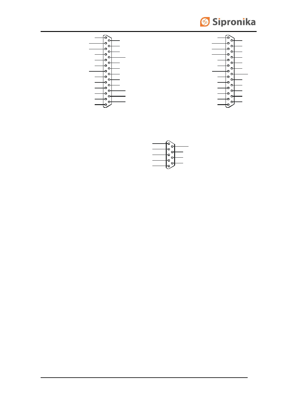
Connector OUT
1
14
2
15
3
16
4
17
5
18
6
19
7
20
8
21
9
22
10
23
11
24
12
25
13
OUTPUT TLX/20 mA -
OUTPUT TLX/20 mA +
OUTPUT TLX/RS232
GROUND
INPUT RX_INF/RS232
INPUT RX_INF/20 mA +
INPUT RX_INF/20 mA -
Connector RELAY
1
6
2
7
3
8
4
9
5
ON1
COM1
OFF1
ON2
COM2
OFF2
Connector PC IN
TXD (PC)
GROUND
RXD (PC)
1
14
2
15
3
16
4
17
5
18
6
19
7
20
8
21
9
22
10
23
11
24
12
25
13
DTR (PC)
RTS (PC)
Fig. 8:
The pins on the display's connectors.
Advertising