3 operation, 1 switch mode, 2 multiplexer mode – Nevion ETH-1000-SW-10G User Manual
Page 6: 3operation
ETH1000-SW-10G
Rev. E
nevion.com | 6
3
Operation
3.1 Switch mode
With DIP1 set to OFF, the board works as a normal Ethernet switch, routing traffic between
all ports based on MAC addresses. See figure 1 for block diagram.
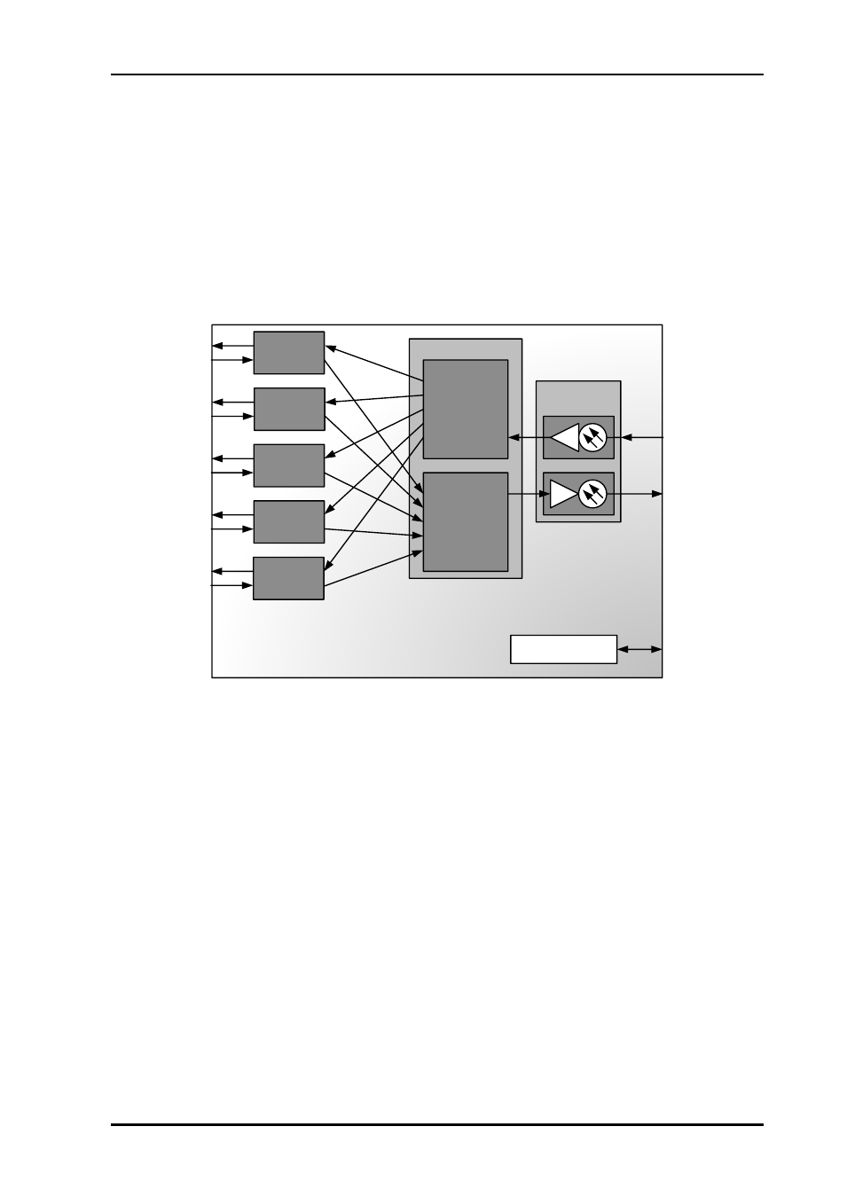
3.2 Multiplexer mode
With DIP1 set to ON, the board becomes an Ethernet aggregator, through the use of VLAN
tags. See figure 2 for block diagram in this mode.
Ethernet switch
Microcontroller
10G uplink port
Remote control
SFP+
De-
multiplexer/V-
lan de-tagging
Port 1
10/100/
1000Base-T
10/100/
1000Base-T
10/100/
1000Base-T
10/100/
1000Base-T
10/100/
1000Base-T
Port 2
Port 3
Port 4
Port 5
Multiplexer/V-
lan tagging
Figure 2 Block diagram of the ETH-1000-SW-10G in MUX mode
Each Ethernet port/stream is VLAN tagged at the input and presented in an aggregated
port/stream at the 10G network port. On the incoming 10G network port/stream the VLAN is
removed and sent to the corresponding Ethernet port. No traffic from one gigabit port is
allowed to enter another gigabit port inside the product. The VLAN tags used are marked as
“0x8800” instead of the usual “0x8100” so that existing VLAN tags will pass through
unnoticed. There should therefore not be any problem mixing the MUX mode with an existing
VLAN setup.