2 rotary switch and push buttons, 3 slide switches – Nevion DAC-AVA-DMUX User Manual
Page 20
DAC-AVA-DMUX
Rev. A
nevion.com | 20
- Remove power and set DIP 15 back to the normal position (‘off’)
- Power up the card once again. The operation of the card will immediately reflect the
freshly loaded default settings. However, the card must be kept powered for at least
10 seconds to ensure that these settings are stored locally to be retrieved again at the
next start-up. The card
’s operational environment must also be kept static during
those 10 seconds (i.e. no change in incoming video standard, no commands issued).
Failing to meet this requirement could result in an incomplete reset and require the
user to start the factory reset sequence over again.
4.2.2 Rotary switch and push buttons
The rotary switch, labeled DLY, adjusts the phase delay from -5 to +4 video lines. It is only
functional when a sync signal, black & burst or tri-level, is present at the sync input. The
rotary switch is accessible from the front of the board.
The push buttons, labeled INC and DEC, are used to fine adjust the phase delay by
samples. It can adjust ±½ video line for the current video standard (or the last video
standard the board was able to lock to). Pressing a button and keeping it pressed will
accelerate the change. The LED adjacent to the button will flash for a short period of time
when the end of the adjustment range has been reached. Pressing both buttons at the
same time will return to the middle of the adjustment range, and the board will acknowledge
by flashing the INPUT and SYNC LEDs simultaneously.
4.2.3 Slide switches
The two switches at the top of the module (rear side) switch between AES out and Data
out. It DC couples the output signal when in DATA out mode, and AC couples the signal
when in AES mode.
Note that to enable Data link output on the AES connector it is also necessary
to set DIP 8 to the Off position when the board is in Manual mode (DIP 16 =
On), or when the board is in Gyda mode (DIP 16 = Off), to select Data link over
AES output in Gyda. Slide switches moved to the right routes out AES.
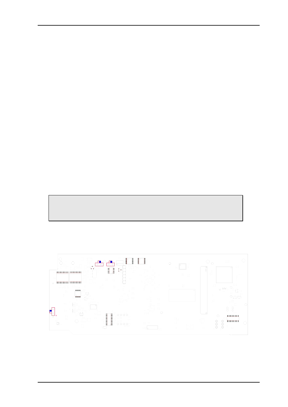
The switch on the left card edge switches between backplane sync input and Flashlink
distributed sync (Future feature upgrade of Flashlink frame). Switch moved up routes the
backplane sync to the card.
Figure 11: The figure shows a bottom view component printout of the board. Note the
location of the slide-switches.