5 switch 6 & 7, Switch, Function description – Nevion ADC-SDI User Manual
Page 13: Default adaptive 3-line comb filter selection, Fixed 2-line comb filter, No comb filter, Luma filtered with chroma trap, Chroma low pass filtered, Table 4: luma / chroma separation filter, 6 switch 8 - reset to factory default
ADC-SDI
Rev.
6
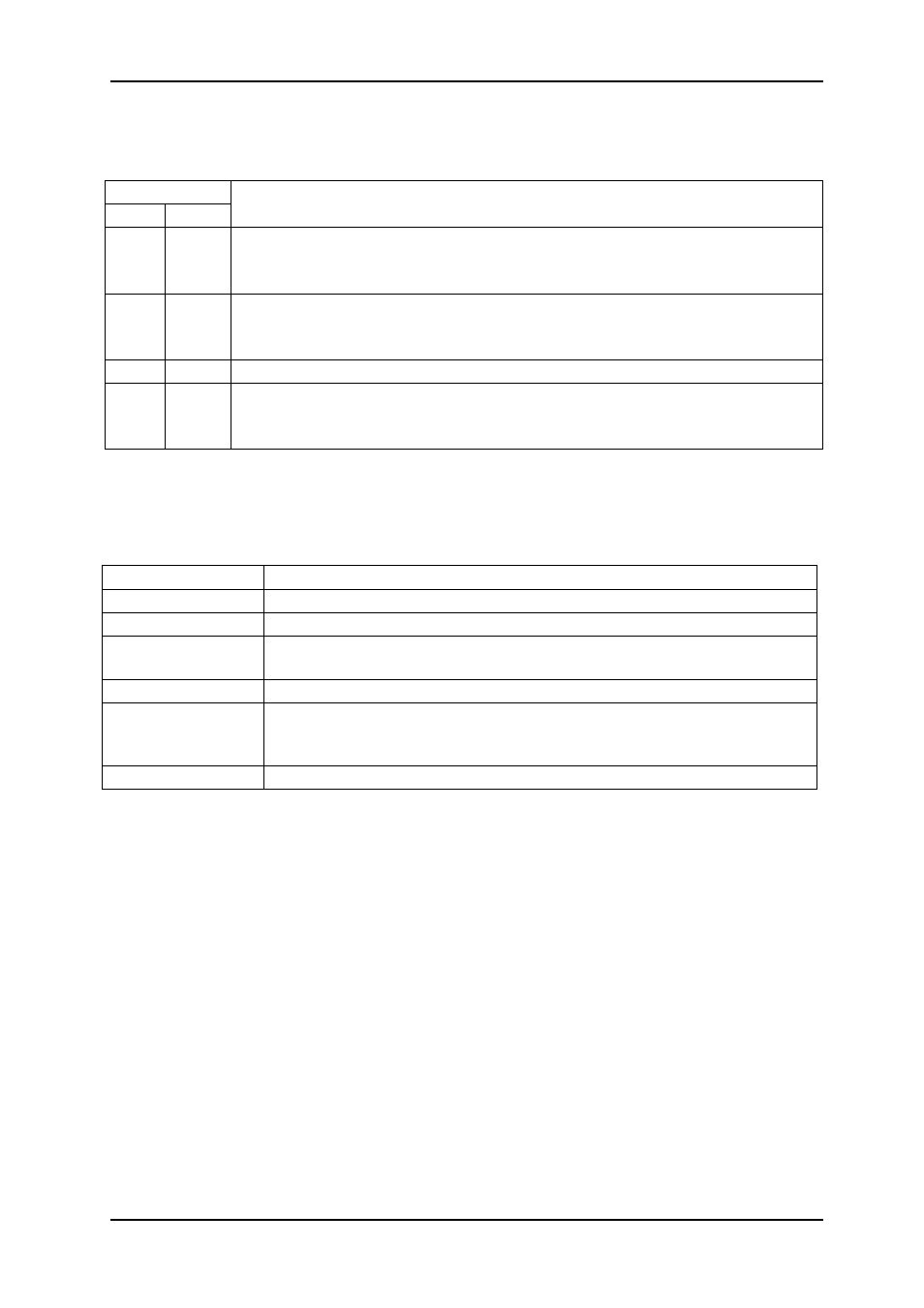
5.2.5 Switch 6 & 7
These two switches determine which Luma / Chroma separation filter that are in selected,
according to Table 5. The factory settings are switch 6 set to on and switch 7 set to off.
Switch #
6 7
Function description
0
0
Default adaptive 3-line comb filter selection.
NTSC adaptive comb with filter coefficients (¼, ½, ¼)
PAL adaptive comb with filter coefficients (½, 0, ½)
1
0
Adaptive 3-line comb filter selection with optional filter coefficients
NTSC adaptive comb with filter coefficients (½, 0, ½)
PAL adaptive comb with filter coefficients (¼, ½, ¼)
0
1
Fixed 2-line comb filter
1
1
No comb filter
Luma filtered with chroma trap
Chroma low pass filtered
Table 4: Luma / Chroma separation filter.
5.2.6 Switch 8 - Reset to factory default
ADC-SDI contains EEPROM that is affected by your choices. Switch 8 is implemented to
reset the EEPROM to factory default. Its use is shown in Table 5.
Action Comment
Power down
Turn switch 8 on
Power up
ADC-SDI enters a special state where the EEPROM is restored to
factory default values. This is flagged by the LEDs, they are all yellow.
Power down
Turn switch 8 off
If you want the DIP switches to be placed in the factory default
position, this is the time to do so: Turn switches 1 through 9 to the off
position. Switch 10 should, as always, be turned to the on position.
Power up
The card EEPROM is now reset to factory settings.
Table 5: A method to restore the ADC-SDI card to the factory settings. Remember to let some
seconds pass by each time you power down, to allow capacitors to be fully discharged.
5.2.7 Switch 9 –Chroma Blanking for Teletext
Switch 9 is enabling Chroma Blanking within the vertical blanking area. When on, the chroma
information in lines 1-23 / 313-335 (PAL) or 1-21 / 263-284 (NTSC) will be erased (replaced
with 0x200). This is an important setting when using ADC-SDI with teletext information in line
23 (like for PAL+). When switch 9 is off, the vertical blanking area will be optimised for video
information.
When using ADC-SDI with S-Video (Y/C), it is recommended to leave switch 9 in off position
Factory setting is switch 9 in off position.
5.2.8 Switch 10 - Programming mode
Switch 10 is purely used for service upgrade of the ADC-SDI card. It should always be in the
on position. If switch 10 is in the off position, the CardState LED will light up red, and the
ADC-SDI card will enter programming mode. This causes no harm, but the card will not work
in this mode.
Factory setting is switch 10 in on position.
network-electronics.com
|
13