4 connections, Figure 2: adc-sdi-c1 connector module, 1 mounting the connector module – Nevion ADC-SDI User Manual
Page 9: 2 correspondence of connectors and signals, The adc-sdi-c1 connector module has 7 bnc's, Analog input: cvbs or s-video luma, Analog input: cvbs or s-video chroma, Dup1, Passive loop through ch1, Dup2
ADC-SDI
Rev.
6
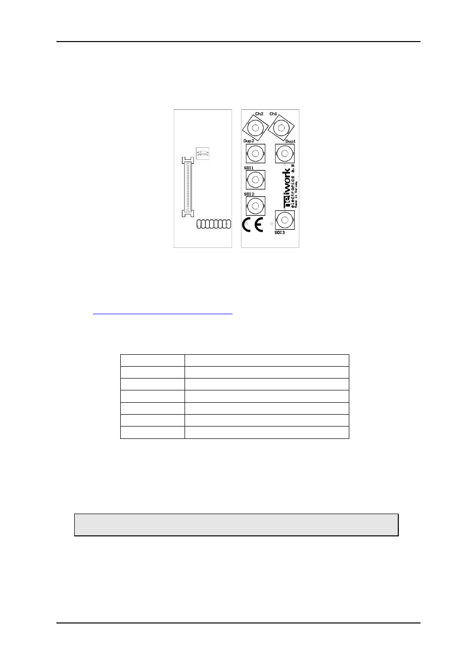
4 Connections
The ADC-SDI has its own connector module: ADC-SDI-C1, mounted at the rear of the sub-
rack.
Figure 2: ADC-SDI-C1 connector module.
4.1 Mounting the connector module
If the connector module is purchased separately, it should be mounted as described in the
user manual for the sub-rack frame FR-2RU-10-2. This manual is also available from our
4.2 Correspondence of connectors and signals
The ADC-SDI-C1 connector module has 7 BNC's:
Ch1
Analog input: CVBS or S-Video Luma
Ch2
Analog input: CVBS or S-Video Chroma
Dup1
Passive loop through Ch1.
Dup2
Passive loop through Ch2.
SDI1
Digital SDI output
SDI2
Digital SDI output
SDI3
Digital SDI output
The analogue input BNC's can be used with CVBS, one at a time, or together with S-Video
Luma on Ch1 and Chroma on Ch2. SDI1, SDI2 and SDI3 are equivalent SDI outputs.
The backplane has a DIP-switch with two individual switches, as shown in Figure 2. Switch 1
is used to turn on/off 75 ohm termination on input channel 1, and switch 2 is used to turn
on/off 75 ohm termination on input channel 2.
The analogue input must be terminated somewhere to enable the video decoder
chip.
network-electronics.com
|
9