1 product overview, 1 quick start guides for adc-sdi, 1 without gyda controller – Nevion ADC-SDI User Manual
Page 4: Insert adc-sdi into a slot in the sub-rack, 2 with gyda controller
ADC-SDI
Rev.
6
1 Product overview
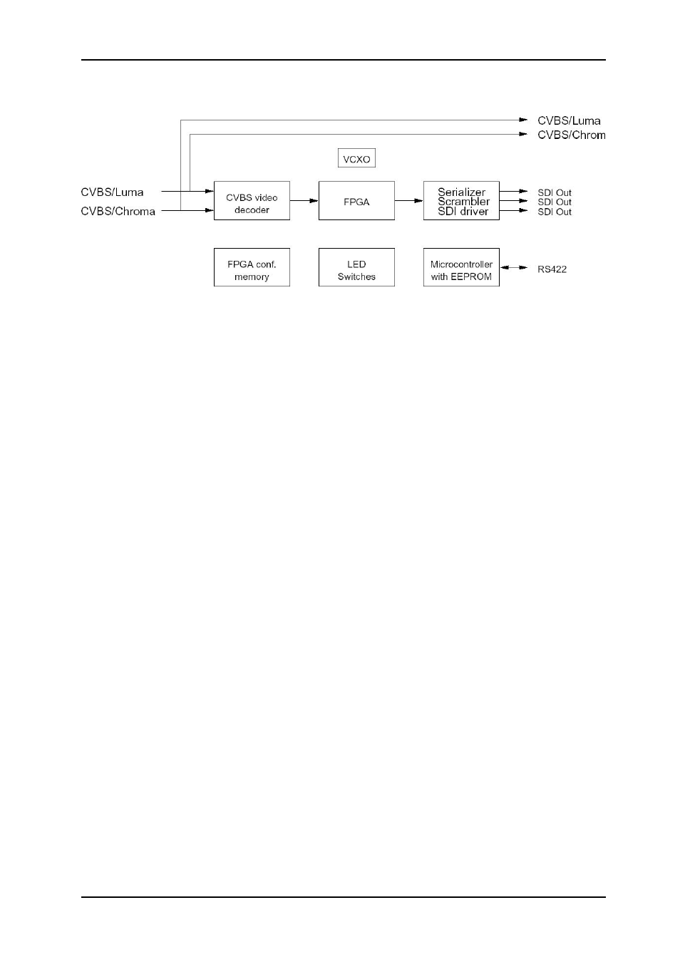
Figure 1: Simplified block diagram of the ADC-SDI card
The Flashlink ADC-SDI is a high-quality 10-bit NTSC/PAL composite 4:2:2 to digital video
converter.
ADC-SDI user parameters can be changed via switches on the unit, or via the GYDA control
interface.
To aid digital to analogue conversion of the digital output the ADC-SDI may generate a white
pulse to mark first field of an 8-field-PAL/4-field-NTSC signal. If the digital to analogue
converter is able to detect this, it will synchronize to the correct field (8-field-PAL/4-field-
NTSC) when synchronizing to an external Black & Burst-generator. The Flashlink DAC-SDI
is able to do this.
1.1 Quick Start Guides for ADC-SDI
1.1.1 Without GYDA controller
1. Attach Analogue input (CVBS or S-Video) and SDI-output to the backplane module
(see Figure 2).
2. Set DIP-switch 1 on (towards backplane), switches 2 and 3 according to the Input
Channel search-mode you want (see Table 3).
3. Insert ADC-SDI into a slot in the sub-rack.
4. Power on. After some seconds the ADC-SDI should be running, and the input should
be detected. No LED should be red and the SDI output should be active. If this is not
the case, please see section 5.1.
1.1.2 With GYDA controller
1. Attach Analogue input (CVBS or S-Video) and SDI-output to the backplane module
(see Figure 2).
2. Insert ADC-SDI into a slot in the sub-rack.
3. Power on. After some seconds the ADC-SDI should be running, and the input should
be detected. No LED should be red and the SDI output should be active. The card
settings should be as the previous time power was applied.
4. Communication with the card is described in section 5.3.
network-electronics.com
|
4