NIStune Type 5 User Manual
Page 9
Advertising
Type 5 Hardware Installation Manual
Page 8 of 15
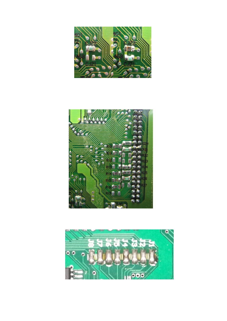
• K11 Micra CG10/CG13 ECU
Move jumper CJ22 to CJ21
Move SMD resistors R10-R17 across to R20-R27. Note that not all positions have resistors.
Notes: R20 = 102, R21 = 000, R22 = Open, R23 = Open, R24 = 102, R25 = 301, R26 = 000,
R27 = Open
Note that the Type 5 board requires all resistor positions R1-R8 on the board to be connected
using solder (blob each position)
Advertising