Ò³ãæ 24 – Onwa Marine Electronics KAP-833 User Manual
Page 24
3
6
Installation of Rudder Feedback
(RFUH standard supplied)
Position
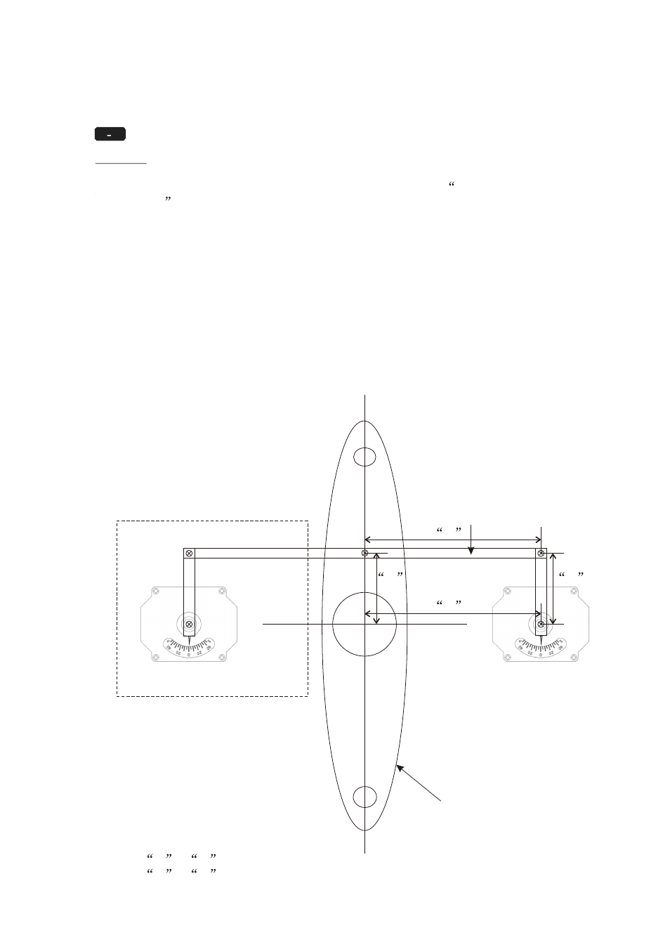
Install rudder feedback as shown in the diagram labelled
Rudder Feedback Unit
Installation
The unit should be adjacent to the tiller and must copy the angular
movement of the tiller. The markings on the rudder feedback unit indicates the
required movement of the tiller for course correction. It should be installed with
the shaft uppermost, mounted and linked in such a way that the four pivot points
(tiller post, feedback shaft and the adjustable linkage points) form the four corners
of a parallelogram.
The rudder feedback unit is water resistant. However, if it is to be mounted in a
wet position, some effort is necessary to ensure the unit does not become
immersed in water. If necessary the rudder feedback unit may be mounted upside
down, in which case the blue and red (or brown) connections to the KAP-833
terminal strip should be reversed.
19
Optional
Rudder feedback unit
Rudder
Connection Arm
X
X
Y
Y
X
=
X
Y
=
Y