Introduction, Peripheral connections – Sierra Video 507144-00 User Manual
Page 2
Digital Mixer User’s Guide
2
Introduction
The DigiLinx Digital Mixer performs dissolve functions between two 270 Mbps component serial digital
video signals. The output can also perform a 'fade to black' operation using either externally provided
video source and internally generated 'black' signal. Dissolve rates are user programmable via an
RS232/RS422 control port and transitions can be triggered via the same control port or one of nine
General Purpose Input(GPI) pins which are activated by way of simple connections to ground.
Both inputs to the mixer are automatically retimed to an adjustable phase sync generator synchronized to
an external analog video reference. The auto-timers have a +/- 1/2 line correction range relative to the
adjustable phase reference. Delay through the mixer is roughly 0.5H (assuming inputs are centered in
their auto-timing range).
Analog reference to internal reference timing is adjustable via local controls or SmartLinx control points;
including Windows PC's, the 1RU frame control panel, and the Alpha One controller. SmartLinx
controllers also have the ability to set dissolve ratios and to trigger transitions. The mixer is a 'two slot'
DigiLinx module; providing a rear panel 25 pin D connector for direct access to GPI's and local serial
control.data) .
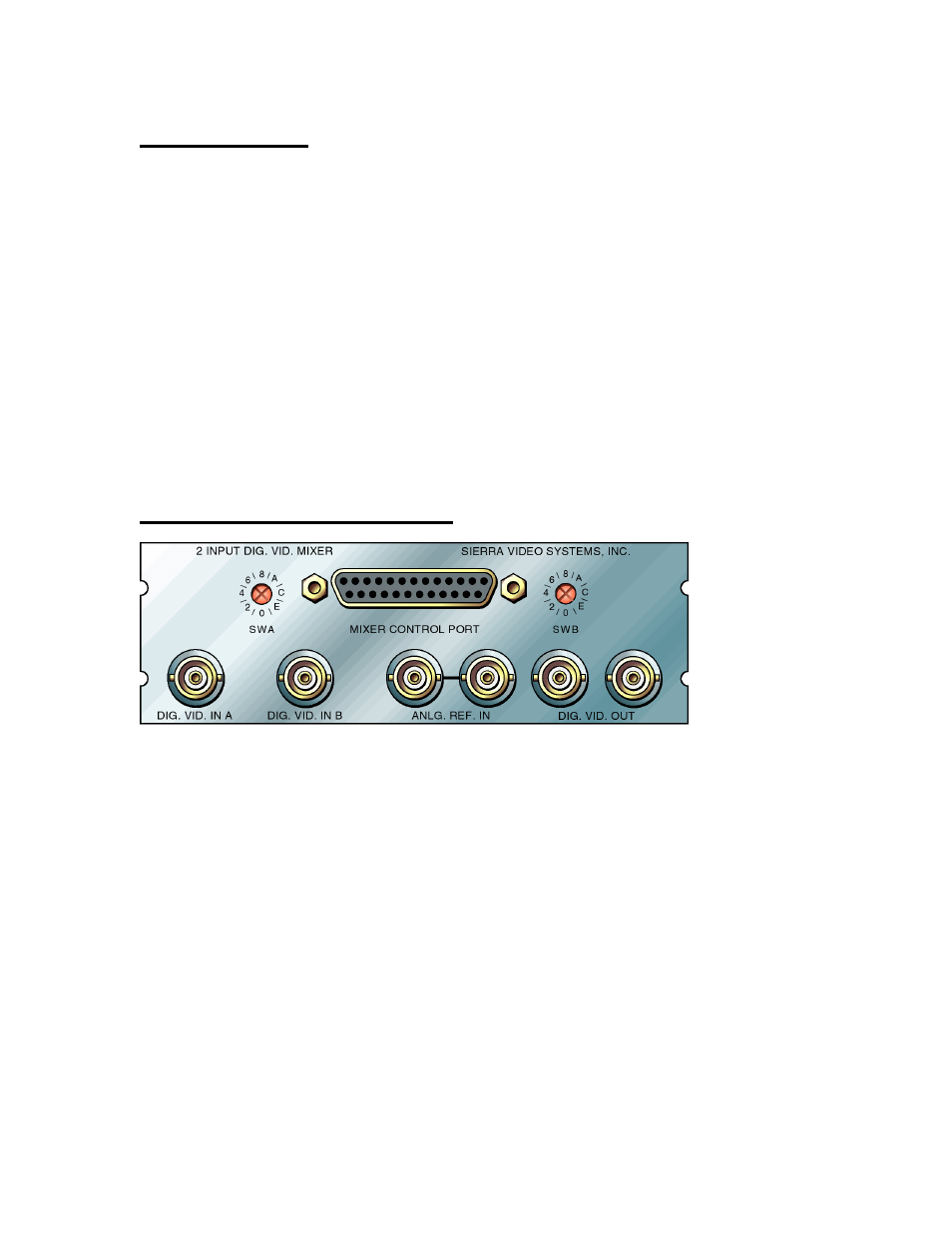
Peripheral Connections
The rear panel provides the following signal connections to the user:
DIG. VID. IN A - This BNC connector serves as a 270Mbps SMPTE 259M signal input to the
product. Signals applied here are fed to the mixer and, optionally, to the clock generation
circuitry for the module.
DIG. VID. IN B - This BNC connector serves as a 270Mbps SMPTE 259M signal input to the
product. Signals applied here are fed to the mixer.
DIG. VID. OUT - These two BNC connectors provide 270Mbps SMPTE 259M signal outputs from
the product. They are copies of one another and either may be used without affecting the other.
ANLG. REF. IN - These two BNC connectors are wired to one another and provide
synchronization inputs to the product. 0.3 to 2V p-p composite sync or video with or without
color burst must be provided as a reference for video output timing. If the reference signal is
not being ‘looped through’ to another load, the unused input should be terminated with 75
Ohms.
MIXER CONTROL PORT - This 25 pin female ‘D’ connector provides access to an
RS232/RS422 serial data control port and to 9 General Purpose Input control pins which are
grounded by the user to trigger transitions. The following table describes the pin assignments
for this connector: