Main module daughter card, Figure 8 – power generation and distribution – Sundance SMT390-VP User Manual
Page 20
Version 2.4
Page 20 of 55
SMT390-VP User Manual
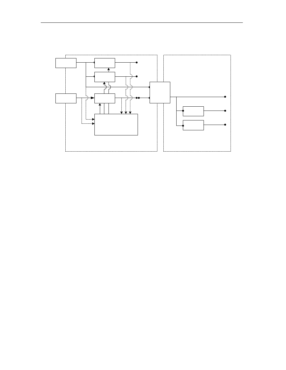
The MSP430 distributes the reset to the daughter board. The following diagram
illustrates the power distribution and the reset distribution on the SMT390-VP:
Main Module
Daughter Card
TIM Connector
D+5V0_IN
D+3V3
TIM
Mounting Hole
D+3V3_IN
Analog Power
Switch
D+2V5
D+1V5
Main Module to
Daughter Card
Power
Connector
D+3V3
Analog Filter
Vadcio
DC / DC
Converter
A+3V3
D+2V25
MSP430
Microprocessor
Vccint
DC / DC
Converter
Vccaux
DC / DC
Converter
On / Off
Control
Voltage
Measure
Voltage
Measure
Figure 8 – Power Generation and Distribution
MSP430 Functionality
The MSP430 implements analog control functionality that is difficult to implement in
the FPGA. The microprocessor
• Controls the power start-up sequence
• Controls the reset structure on the module
The following diagram shows what the default microcontroller boot code does: