Figure 1 – module trigger structure – Sundance SMT391-VP User Manual
Page 13
Advertising
Version 1.3
Page 13 of 41
SMT391-VP User Manual
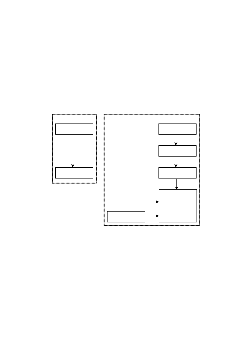
When the SMT391-VP receives a trigger, the SMT391 interface block gets activated
and starts capturing the samples sent by the ADC.
Connector J9 should be used to externally trigger the acquisition of both channels I
and Q.
Connector J10 should be left unconnected.
The following diagram is a graphical representation of the trigger structure and
sources on the SMT391-VP:
FPGA
External Trigger
LVPECL
Buffer
External Trigger Input
(MMBX)
ComPort Rx Cmd
State Machine
ComPort Interface
Trigger Generation
Trigger
Distribution
Trigger Setup
Register
Figure 1 – Module Trigger Structure.
Advertising