Appendix – Sundance SMT391-VP User Manual
Page 33
Version 1.3
Page 33 of 41
SMT391-VP User Manual
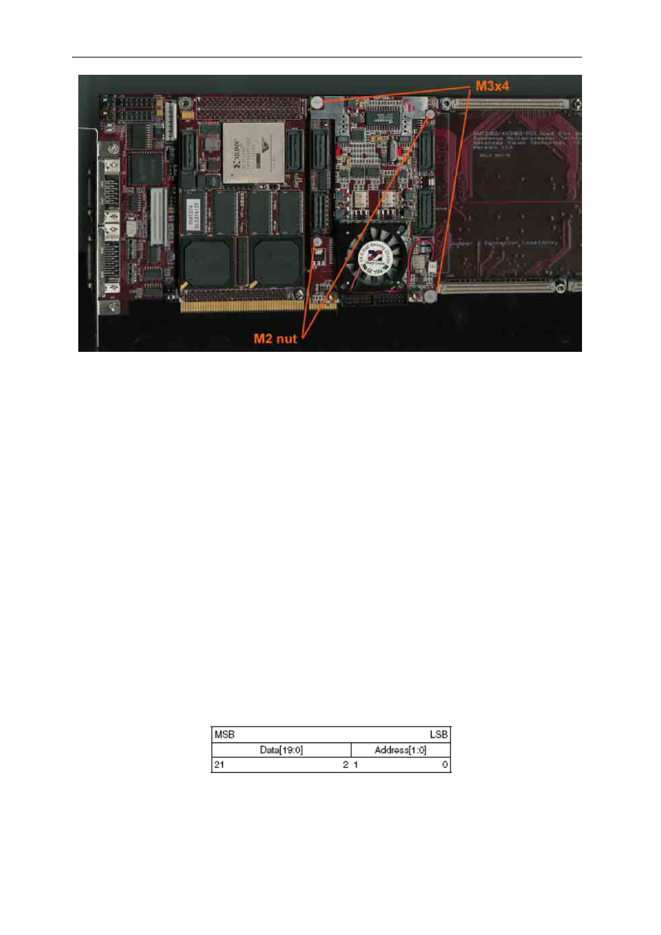
Figure 20 – Connecting the SMT391 to the SMT338-VP
Configuring the FPGA
A microcontroller MSP430 is connected to the comport 3 of the SMT391-VP. The
MSP430 received the bitstream of the FPGA from the comport 3 and then configures
the FPGA with it.
Refer to the SMT6500 user guide for the details of the configuration of the FPGA.
Appendix
PLL (LMX2330U) interface
The PLL 22-bit shift register is loaded via a microwire interface. This interface
consists of 3 wires. The shift register consists of a 20-bit Data[19:0] Field and a 2-bit
Address[1:0] Field. The Address Field is used to decode the internal control register
address. When LE transitions HIGH, data stored in the shift register is loaded into
one of 4 control registers depending on the state of the address bits. The MSB of
Data is loaded in first. The register is shown in the following figure.
Figure 21 – Register Setup for PLL.