Rear panel description, Front panel description – System Fidelity SA-370 User Manual
Page 10
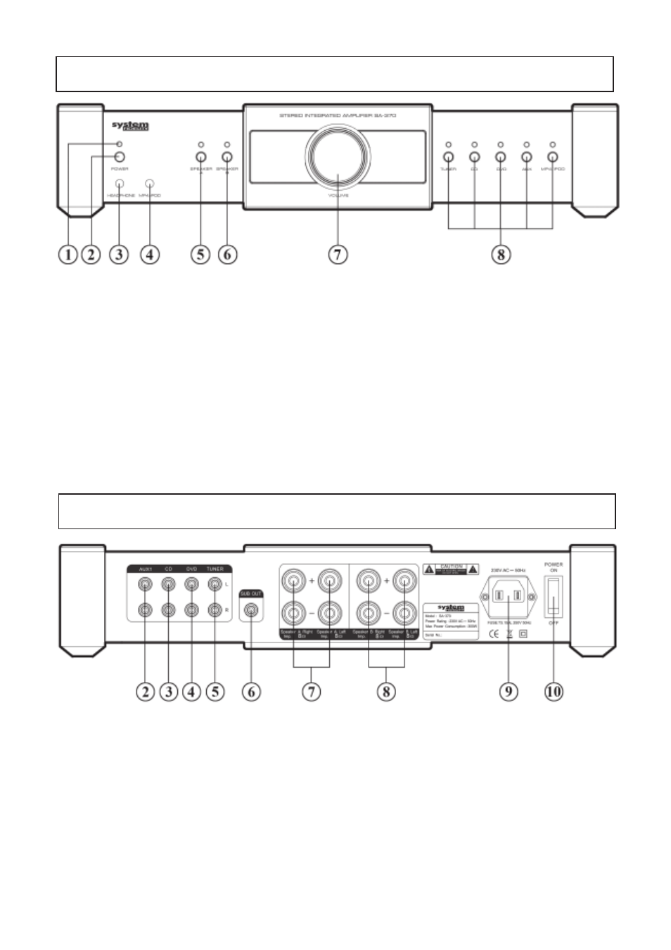
(1) LED indicator: indicates the stand-by mode
(2) Stand-by power switch: Used to switch the amplifier on and to stand-by.
(3) Headphone output jack: 3,5-mm jack that suits most headphones.
(4) MP4/iPod input: 3,5mm jack for connection of iPod or MP3 and MP4 player.
(5) Speakers A: switches on or off the main speaker pair.
(6) Speakers B: switches on or off the additional speaker pair.
(7) Volume knob: by turning the knob sound volume increases of decreases.
(8) Input source selectors: Activates the source input.
10
REAR PANEL DESCRIPTION
(2) - (5) Line Inputs - RCA cynch inputs for connection of audio source units.
(6) SUB OUT: RCA cynch output for connection of powered (active) subwoofer.
(7) Speakers A: Speaker terminals (left and right speaker) for connection of the main speaker
pair
(8) Speakers B: Speaker terminals (left and right speaker) for connection of the additional
speaker pair
(9) Power cord terminal: for connecting the main lead.
(10) Main power switch: The power on/off switch.
FRONT PANEL DESCRIPTION