Selecting the microphone modeler, Overall settings, Input gain – Teac DM-24 Effects Manual User Manual
Page 12: Output level, Bypass, Selecting the source microphone, Input gain output level bypass, 3 – antares microphone modeling—overall settings
3 – Antares microphone modeling—Overall settings
12
TASCAM DM-24 Effects
Excessive frequency boosting can occur if processes
intervening between the microphone and the modeler
produce noise. This noise will be excessively
boosted, especially if the filtering on the microphone
and the recording process has accentuated this.
Polar response patterns can be simulated, but cannot
automatically change the pattern of the source micro-
phone. For example, if a recording has been made
using a microphone with a cardioid response pattern,
setting the model’s pattern to omnidirectional will
not automatically turn the source microphone into an
omnidirectional microphone (and add the room
ambience that would be present if the microphone
actually was an omnidirectional one).
Likewise, if a source microphone has a particular
off-axis response, this individuality will be retained
even if a different model is selected.
NOTE
The microphone modeler can only be used with the L
input and output of either effect 1 or effect 2. It is not
possible to use the microphone modeler to process two
channels at the same time using one effect.
The microphone modeler is not available in high sam-
pling frequency mode.
Selecting the microphone modeler
Recall the preset library entry 1-100 in order to load
the microphone modeler.
See “Setting up the effects units” on page 7 for fur-
ther details.
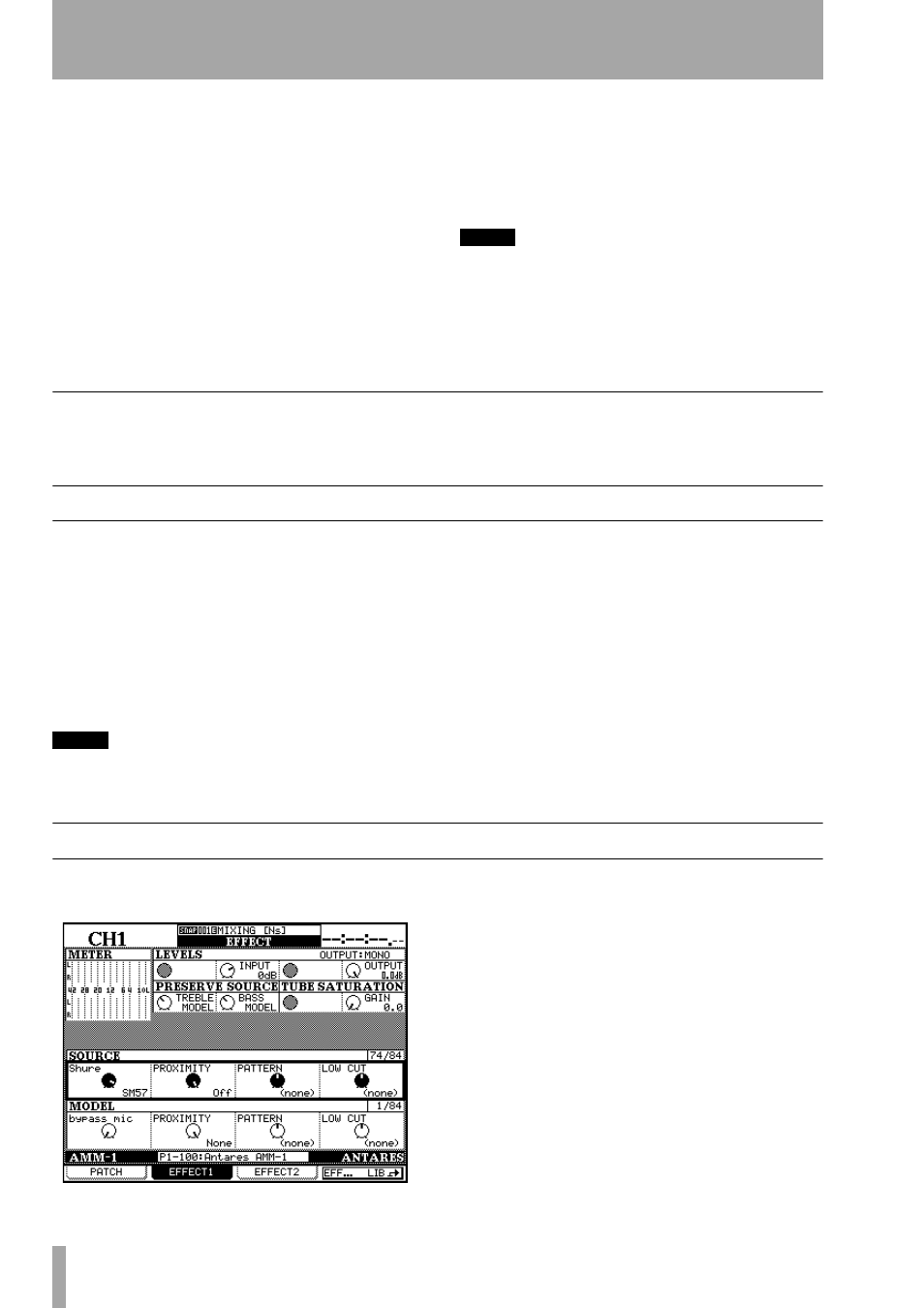
Overall settings
These settings apply to the overall effect (not to the
source or model microphones individually).
Input gain
This (
INPUT
) allows you to set the rela-
tive gain for the input source (top row, POD 2).
Start at 0dB, but you may want to increase the level
slightly to increase the amount of saturation available
to the processor. The signal may be cut by a value up
to –30 dB and boosted by up to 12 dB.
NOTE
Increasing this input level to obtain the highest possible
non-clipping meter level does not result in the improve-
ment in dynamic range that would result if this opera-
tion was to take place on an all-analog system.
Output level
This (
OUTPUT
) allows the overall
output gain from the modeler to be adjusted from
0 dB to –12 dB.
Bypass
This allows the whole of the microphone
modeler to be bypassed for A-B comparisons. It is
not the same as selecting the bypass microphone
model (“The bypass microphone model” on
page 13), which is a “neutral” microphone model for
either source or output (but it is the same as selecting
it for source and output).
Selecting the source microphone
Move the cursor to the
Source Microphone
, selecting
the model using POD 1.
The manufacturer name is given at the top left of the
box, and the model at the bottom right.
There may be two listings for a particular source
microphone model, one of them ending with a
-w
.
This means that this is the model of microphone with
a supplied windscreen (thereby affecting the acoustic
characteristics of the microphone).
There may also be a
(m1)
or
(m2)
following the
microphone name. These refer to different examples
of the same kind of microphone. Pick the one which
is most appropriate for your particular microphone.
If you do not have a microphone listed in the list of
source microphones provided: