4 – connections, Status indicators – Teac FW-1082 Setup Guide User Manual
Page 13
4 – Connections
TASCAM FW-1082 Setup Guide
13
The
MONITOR
outputs are balanced (1/4" jack,
wired as for the balanced inputs), and output signals
at a nominal +4 dBu, with an impedance of 100
Ω.
These should be connected to a monitoring system.
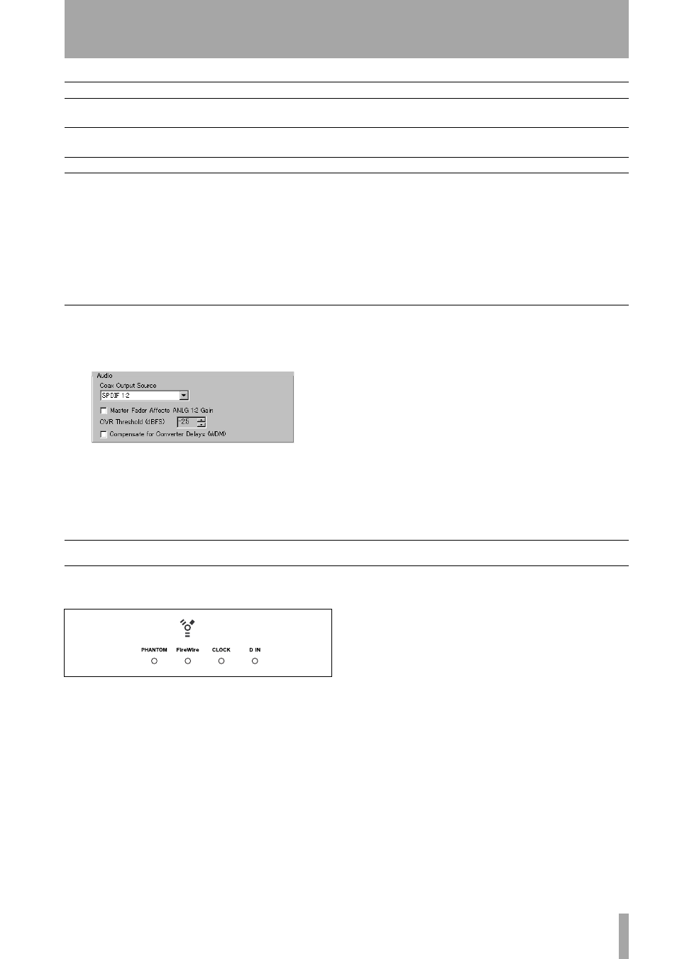
A note on output
In the software Control Panel, there are a number of
options that you can set.
The master fader can be set to control the level of the
two analog outputs in monitor mix mode (if this is
turned off (default), the master fader affects the mas-
ter stereo bus level inside the DAW software, but not
the level output from the balanced outputs in monitor
mix mode).
The threshold at which the
OL
signal indicators light
to show an overload can be set using the control here.
It can be varied between 0.0 and –5.0 dBFS, in 0.5
dBFS increments.
Also, the S/PDIF digital outputs can be set to mirror
the analog monitor outputs (allowing you to record to
a 2-track master recorder while monitoring through
the analog outputs) or be independent of them.
Status indicators
The four green status indicators show the current sta-
tus of:
•
PHANTOM
Whether the phantom +48V power is
turned on for
MIC
inputs 1 through 4.
•
FireWire
The IEEE.1394 connection.
•
CLOCK
The system clock.
•
D IN
The stereo digital input from the coaxial input.
When these indicators are lit, it means that the appro-
priate connection has been made and the signal is
being received properly.
A flashing
FireWire
indicator shows that there is an
error in the IEEE.1394 connection.
No indicator means “no connection” for all indica-
tors except
CLOCK
. If any of the other three indica-
tors are flashing fast, this shows an input error. A
slowly flashing indicator indicates a lock problem.
Output level
—
—
–2 dBu (maximum +14 dBu)
Input impedance
2.2 k
Ω
10 k
Ω
a
10 k
Ω
Output impedance
—
—
100
Ω
a. Channel 8 can be switched to
GUITAR
impedance at 500 k
Ω using the
GUITAR | LINE/MIC
switch on the rear
panel.
MIC
LINE IN (BAL)
INSERT
Table 4.2: Specifications of analog audio I/O
Figure 4.3: Audio output options in the Control
Panel
Figure 4.4: Indicators