2–names and functions of parts, Bottom panel – Teac LA-40MKIII User Manual
Page 7
TASCAM LA-40MKIII
7
2–Names and Functions of Parts
Bottom panel
y
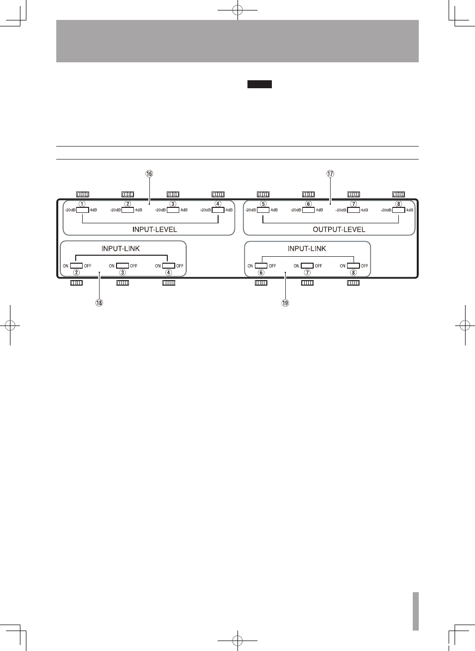
INPUT LEVEL switches 1–4
Switches that set whether the signal levels intput
to the
INPUTS
8 are +4 dBu (1.23 V) or -20 dBu
(0.0775 V). This setting can be made for each
channel independently.
u
OUTPUT LEVEL switches 5–8
Switches that set whether the signal levels output
from the
OUTPUTS
7 are +4 dBu (1.23 V) or -20
dBu (0.0775 V). This setting can be made for each
channel independently.
i
INPUT LINK switches 2–4
These switches allow an input signal to be routed
to any higher numbered output from 2–4. Two
or more inputs can also be assigned to multiple
outputs in sequence (see “3–ADA Functions” for
examples.)
o
INPUT LINK switches 6–8
These switches allow an input signal to be routed
to any higher numbered output from 6–8. Two
or more inputs can also be assigned to multiple
outputs in sequence (see “3–ADA Functions” for
examples.)
r
Power outlet (see NOTE below)
Use this three-prong outlet, which is not affected
by the power switch, to connect AC equipment
with a maximum power consumption of 400 W
(or 3A). This connector is convenient when using
multiple LA-40
MK
III units. The specifications are
displayed on the top of the unit.
NOTE
The EUR model does not have this power outlet, so the
panel here is blank.
t
AC IN connector
Connect the included power cord.
E_LA-40mkIII-OM_RevC.indd 7
08.12.19 1:03:23 PM