Tendzone TYCHO T 1212/CA User Manual
Page 15
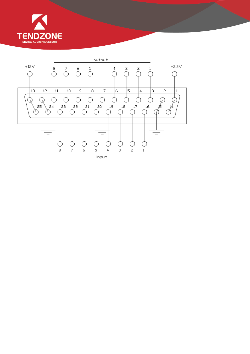
B. Definition and Wiring Demonstration of the GPIO Terminals
Two usages of GPIO:
The first usage is to output electrical level RO (RO 1~4 and RO 5~8), which means when the any parameter of the inside of
the matrix changes (for example, certain channel is muted), output level of certain GPIO output pin will change
subsequently and drive the external circuit;
Notes: RO 5~8 can only be connected to 12 V (can only be used with PIN-13 and PIN-25), and their outputs are OC outputs,
their electrical levels are switchable, their driving current is high, and they are usually used to drive relays, buzzer or other
devices with high power consumption; and outputs of RO 1~4 are ordinary electrical level outputs. The maximum output
current is 0.4 mA when it outputs the high level and -30 mA when outputs at low level.
Inside of the audio matrix changes → electrical level of certain GPIO pin changes → driving external circuit.
The second usage is input RI (RI 1~8), which means when the external circuit changes, the level of certain GPIO input pin
will change subsequently and trigger certain parameter of the matrix to change.
State of external circuit changes → level of certain GPIO pin changes → certain parameter of the inside of the matrix
changes
Wiring Method of Output RO 5~8
Notes: RO 5~8 can only be connected to 12 V (can only be used with PIN-13 and PIN-25), and their outputs are OC outputs,
their levels are switchable, their driving current is high, and they are usually used to drive relays, buzzer or other devices
with high power consumption.
The 12 V reference OC output can be switched to 12 V output to be used as 12 V triggering signal for the linkage fire
control.
- TYCHO T 440/TC TYCHO T 880/TC TYCHO T 1208/TC TYCHO T 1212/TC TYCHO T 880/C TYCHO T 1212/C TIMON 8 User Manual TIMON 16 User Manual TIMON 20 User Manual TIMON 32 User Manual TIMON 8 Cobra User Manual TIMON 16 Cobra User Manual TIMON 32 Cobra User Manual SOLON M880/EX SOLON M1616/EX SOLON M880/Cobra SOLON M440/Cobra SOLON M1616/Cobra SOLON M1208/Cobra SMART 1616 Series