Tendzone TYCHO T 1212/CA User Manual
Page 16
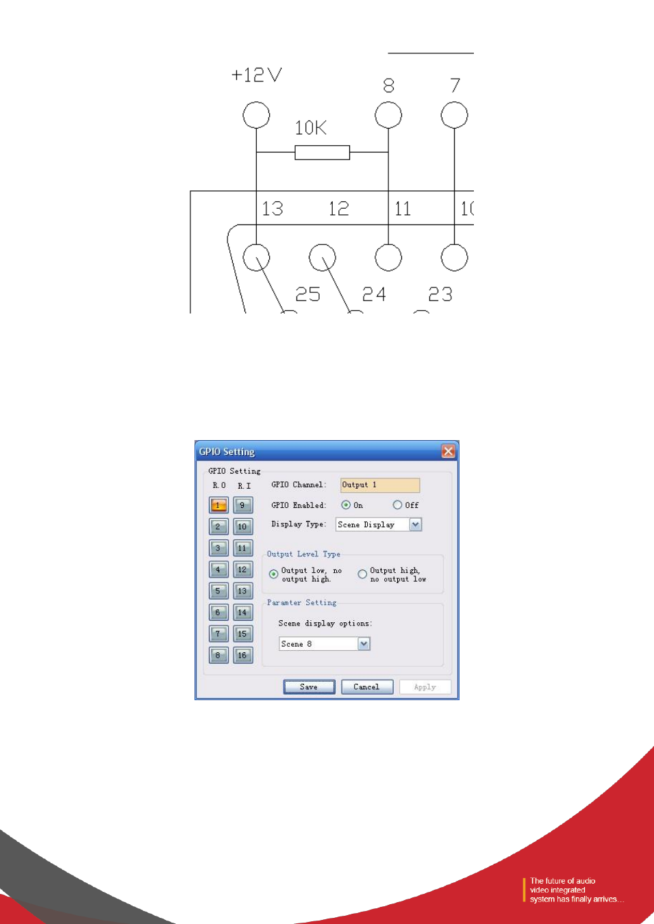
Notes: a 10 k resistance should be connected between PIN-13 and any of the RO 5~8 to switch the OC output to 12 V. As is
shown in the chart, PIN-13 outputs constant 12 V voltage; PIN-11 corresponds to RO 8 that outputs 0 or 1 according to the
changes of the matrix. Such level can be used to trigger another GPIO or other devices.
The following settings should be done on the PC after the GPIO is connected in accordance with the above methods:
After the device is connected to the PC → enter the GPIO Control interface → click RO 8:
(1)
If the Scene Display is selected, the scene loading is selected, the scene parameter is “Scene 8”, the output
electrical level is “output low,no output high ”, and the GPIO Enabled State is “ON”.
The settings will become effective after the “Apply” button at the bottom is clicked.
- TYCHO T 440/TC TYCHO T 880/TC TYCHO T 1208/TC TYCHO T 1212/TC TYCHO T 880/C TYCHO T 1212/C TIMON 8 User Manual TIMON 16 User Manual TIMON 20 User Manual TIMON 32 User Manual TIMON 8 Cobra User Manual TIMON 16 Cobra User Manual TIMON 32 Cobra User Manual SOLON M880/EX SOLON M1616/EX SOLON M880/Cobra SOLON M440/Cobra SOLON M1616/Cobra SOLON M1208/Cobra SMART 1616 Series