Usdt 3002, Installation, 1 mounting – Thermo Technologies USDT 3002 User Manual
Page 4: 2 electrical wiring
USDT 3002
© 06279 usdt_3002.mon
us.ind
d
|
4
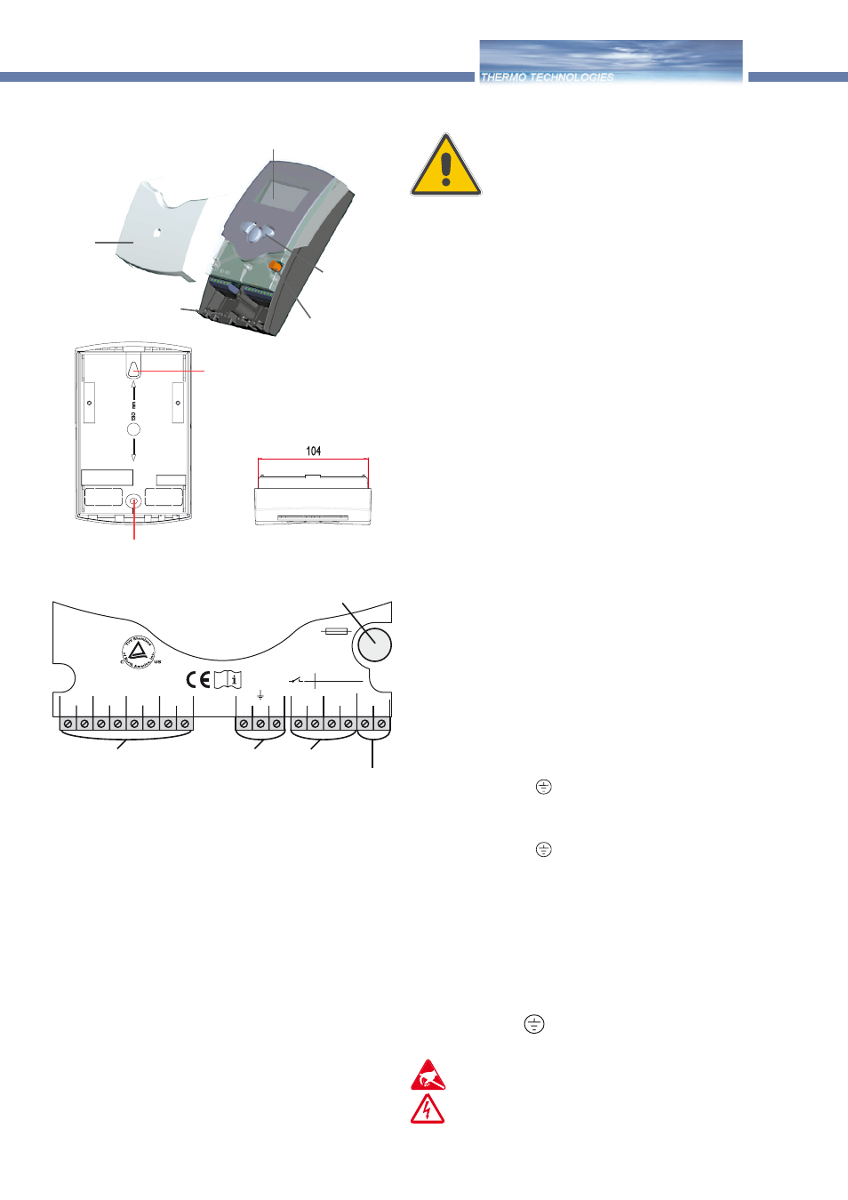
display
pushbutton
can fuse 4A
cable conduits with strain
relief
cover
1.1 Mounting
The unit must only be located internally. It is not suited
for installation in hazardous locations and should not be
sited near an electromagnetic field. The controller must
be positioned 1/8" from walls, LS-switches or fuses. Please
pay attention to a separate laying of the cable lines and
installation of AC power supply.
1. Unscrew the cross-recessed screw of the cover and
remove it from the housing.
2. Mark the upper fastening point on the wall and premount
the enclosed dowel and screw.
3. Hang up the housing at the upper fastening point and mark
the lower fastening point on the underground (hole pitch
5"5 mm), afterwards put the lower dowel.
4. Fasten the housing at the underground.
1. Installation
Warning!
Switch-off power supply before
opening the housing.
1.2 Electrical wiring
The power supply to the controller must be via an external
power supply switch (last step of installation!) and the line
voltage must be 115 Volt (50...60 Hz). Flexible lines are to
be fixed at the housing by enclosed strain relief supports
and screws.
The controller is equipped with 2 relays for connection
to system counterparts e.g. pumps, valves etc. can be con-
nected:
• Relay 1
18 = conductor R1
17 = neutral conductor N
13 = ground clamp
• Relay 2
16 = conductor R2
15 = neutral conductor N
14 = ground clamp
The temperature sensors (S1 up to S4) will be connected
to the following terminals independently of the polarity:
1 / 2 = Sensor 1 (e.g. Sensor collector 1)
3 / 4 = Sensor 2 (e.g. Sensor tank 1)
5 / 6 = Sensor 3 (e.g. Sensor TSPO)
7 / 8 = Sensor 4 (e.g. Sensor TRL)
The power supply terminals are:
19 = neutral conductor N
20 = conductor L
12 = ground clamp
hanging
fixation
Electrostatic discharge can damage electronic
components
Dangerous voltage on contact
1
2
S1
S2
S3
3
4
5
6
Temp. Sensor
Pt1000
L
N
R1
N
R2
N
20
19
18
17
16
15
S4
7
8
14
13
12
2 (1) A 115
2
V~
(1) A 115 V~
R1
R2
T4A
115 V~
net clamps
fuse
consumer clamps
Sensor clamps
earthing clamps