Usdt 3002 – Thermo Technologies USDT 3002 User Manual
Page 7
USDT 3002
© 06279 usdt_3002.mon
us.ind
d
7
|
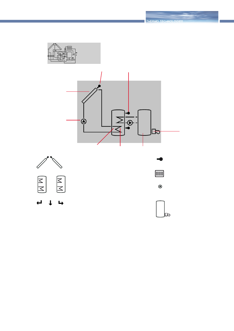
The system screen (active system scheme) displays the full
system operation. It consists of several system component
symbols, which are - depending on the current status of the
system - either flashing, permanently displayed or hidden.
Sensor
Collector 1
Pumps
Additional symbol for
operation of the burner
Tank
Tank heat exchanger
Tank 2 or or 2nd relay option
(with additional symbol)
Sensor tank top
Collectors
with collector sensor
Pump
3-way-valves
The flow direction or the current bre-
aking capacity are always shown.
Heating circuit
Tank 1 and 2
with heat exchanger
After-heating
with burner symbol
Temperature sensor
2.2.3 System screen
only system screen
Constantly green:
System functioning correctly
Red/green blinking: blinking initialisation phase of manual
operation
Red blinking:
sensor defect
2.3 Blinking codes
2.3.2 LED blinking codes
2.3.1 System screen blinking codes
• Pumps blink during starting phase
• Sensors blink if the respective sensor-indication channel
is selected.
• Sensors blink rapidly in case of sensor defect.
• Burner symbol blinks if 2nd relay is activated