4 module leds, 5 fiber optic cable, 6 installation – Thinklogical Velocitykvm T-4200 SDIXtreme 3G+ Module Manual User Manual
Page 8
®
T-Series SDI Modules, Rev. A
8
September 2011
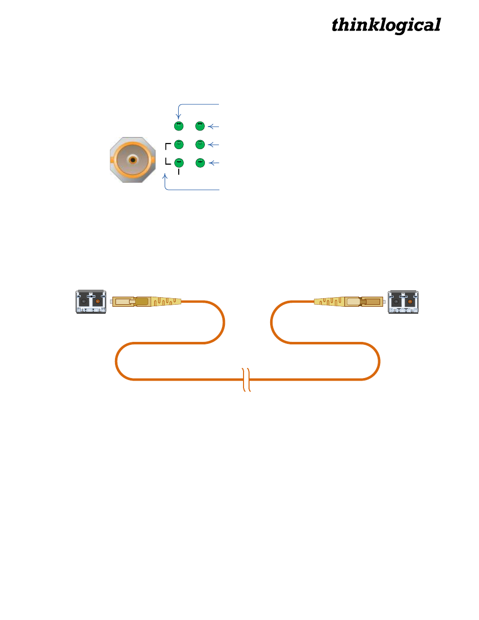
2.4 Module LEDs
The Transmitter, Receiver and Transceiver Modules each feature two pairs of LEDs. Each pair of LEDs
functions as follows:
SDI Module LEDs:
(Operating in HD Mode when lit.)
(Operating in SD Mode when lit.)
(Operating in 3G Mode when both lit.)
SD
HD
CH0
ACT
3G
(Inoperative)
(On Tx, Input signal on BNC when lit.
On Rx, Input signal on Fiber when lit.)
2.5 Fiber Optic Cable
Fiber optic cables connect the Transmitters to the Receivers. Standard multi-mode fiber optic cables
must be 50 or 62.5 microns, terminated with LC type fiber optic connectors. Be careful not to kink or
pinch the fiber optic cable as it is being installed and keep all bend radii to no less than 3 inches
(76.2mm).
Standard multi-mode fiber optic cable (up to 1000 meters),
50 or 62.5 microns, terminated with LC-type connectors
◄Transmit
◄Receive
2.5.1 Single Fiber Operation
The unit will operate with a single fiber from the TX to the RX. In this mode, the TX can transmit video
and data to the RX, but the RX cannot send any information to the TX. (RS-422 data can be transmitted
in the TX to RX direction only.)
2.5.2 Dual Fiber Operation
In this mode video information is transmitted from the TX to the RX over fiber L1 (and L3 in models with
two SFPs). Fiber L2 is used as a data return path from the RX to the TX, allowing full duplex, bi-
directional RS-422 data transfer.
2.6 Installation
All physical connections to the product use industry-standard connectors. Non-supplied cables are
commercially available. All connections are found on the rear of the unit.