Tri Tool 204B Flange Facer User Manual
Page 11
11
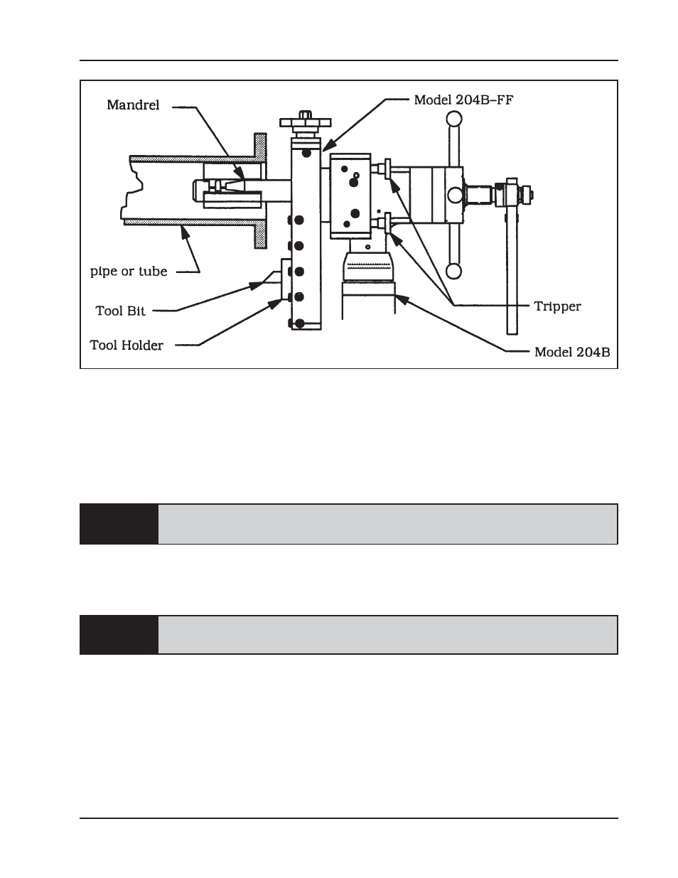
Model 204B-FF Flange Facer
92-0698 : Orig. 970131
NOTE:
CAUTION:
Check for the proper position of the tool holder.
Check for the proper position of the tool bit to the flange.
Check the position of the tripper shaft for feed rate.
Attach the proper power supply line to the model 204B.
If using an air driven assembly, use an adequate in-line filter, regulator and
lubricator.
MACHINING SEQUENCE
Turn the motor on.
The actual machining operation will begin when the cutting surface of the tool bit
comes in contact with the flange.
If the pipe is out of round, the cutting will contact only a small segment of the flange
during each revolution.
To avoid tool bit damage, the tool bit must clear the highest point of the flange on the
first revolution.
After the cut is finished, turn the motor off to stop the Flange Facer rotation.
Loosen the mandrel draw nut and remove the BEVELMASTER
TM
from the pipe.