Verilink 2010 (34-00204) Product Manual User Manual
Page 10
Installation
2-3
2010 CSU
S2-6:
This position enables the sending of an alarm indi-
cation signal (AIS) during an active payload loopback. The
unit can be optioned to generate an alarm indication signal
(unframed all ones) to the DTE during remote loop or to
pass the received network signal to the DTE on remote loop.
A - Generate AIS to DTE
B - Pass signal to DTE
S2-7:
This position enables the sending of a PRM (per-
formance report message) during an alarm indication signal
(AIS). If the unit detects a loss of sync from the DTE, an
unframed all ones signal is generated to the T1 facility. If
Switch S2-6 is set to generate AIS and Switch S1-1 is set
for T1.403 operation, the unit interrupts the AIS signal with
a PRM once a second.
A - PRM enabled
B - PRM disabled
2.5.3
Configuration Switch S3
Switch S3 is a 2 -position slide switch (refer to
It selects the DTE side transmit and receive pair configura-
tion for either a TxPORT (TX) shelf or any other manufac-
turer’s shelf (KX). This switch is factory set and should not
be changed.
2.5.4
ACO/Alarm Card (Option)
The optional ACO/alarm card monitors the ‘NET’, ‘FAR’,
and ‘DTE’ alarm indicators for either an ‘alarm active’ or an
‘alarm clear’ condition and provides closure contact points
on the rear panel. The corresponding front panel LED lights
when an alarm condition is detected.
The alarm card circuitry scans the status (on/off) of the
NET, FAR, and DTE indicators 10 times a second (100 ms
windows). The card declares an alarm if one or more indica-
tors are on for 100 consecutive 0.1 second samplings (10
seconds). When this happens, the red ‘Status’ indicator turns
on until no alarm conditions are detected for more than 100
consecutive 0.1 second samplings (another 10 seconds).
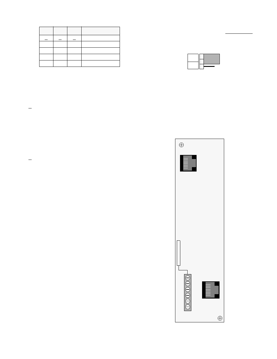
Alarm Relay: The rear panel alarm relay contacts may be
configured as normally open (NO) or normally closed (NC)
depending on the setting of the optional alarm card jumper
S2-3
S2- 4
S2-5
DTE ALBO Level
A
A
A
0-133 feet
B
B
B
134-266 feet
A
B
B
267-399 feet
B
A
B
400-533 feet
A
A
B
534-655 feet
shown below. This 3-pin jumper straps the ACO alarm con-
tact. Position jumper over pins 1 & 2 for normally open
operation (closes on alarm) or over pins 2 & 3 for normally
closed operation (opens on alarm).
NO
NC
1
2
3
Alarm
Relay
2100 Rear Panel
DTE
8
1
8
1
NET
1 + V
2 GND
3 – V
4 FRM GND
5 ALM
6 ALM COM
Figure 2-2
2010 CSU Rear Panel
DB15
Available
1
6
Option
DB15
Available
Option