2 front panel testing, 3 terminal operation – Verilink 2010 (34-00204) Product Manual User Manual
Page 13
3-2
Operation
2010 CSU
following conditions from the DTE: one or more BPVs,
FBEs, CRCs, a yellow alarm, low ones density, or loss of
signal/loss of sync.
3.1.3
Test Controls and Indicators
7)
Loop: This yellow LED lights under the following
conditions: if the manual loop switch is placed in the
‘LOOP’ position, if the unit receives an inband loop code
for > 5 seconds, or if the unit receives an FDL loop message
(PLB or LLB). The LED does not light if the test switch is
placed in the ‘NRM’ position or if an inband or FDL unloop
code is received.
8)
Test Switch: This switch is used for local testing.
for further information.
9)
Test Jacks: Bantam jacks are provided for access to
the T1 line on the DTE side of the CSU. Refer to
for further information.
3.2
Front Panel Testing
The previous section gave a brief description of each front
panel control and LED indicator. This section explains the
front panel test functions. Refer to
for locations.
3.2.1
Test Switch
Local Loop: In the local loop mode (LOOP), the unit loops
the signal from the customer equipment (DTE IN) back to
the customer equipment (DTE OUT). It also loops the
received signal from the T1 facility (NET IN) back to the
T1 facility (NET OUT). When moved back to ‘NRM’, the
local loopback is removed.
Remote Loop: The unit can be looped remotely by generat-
ing towards it a standard CSU line loopback code (00001
repeating for Š 5 seconds, framed or unframed). Once it is
looped, the received signal from the T1 facility (NET IN) is
regenerated and transmitted back to the T1 facility (NET
OUT). The unit can be unlooped remotely by generating
towards it a standard CSU line unloop code (001 repeating
for Š 5 seconds, framed or unframed).
DIP switch S2 configures the unit to either generate an
alarm indication signal (unframed all ones) to the DTE or to
pass the received data from the network to the DTE. The
unit responds to FDL loop (PLB, 0000111011111111) and
unloop command messages (0011100011111111).
3.2.2
Test Access Jacks
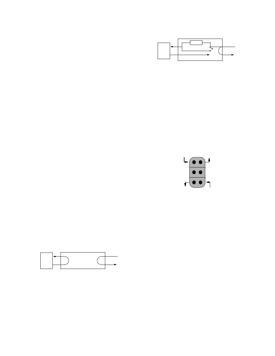
Six bantam test jacks are provided for access to the T1 line
on the DTE side of the CSU. Jacks allow transmit and
receive toward the network, toward the DTE, or monitoring
of traffic between DTE and network. These are customarily
used to inject and receive T1 signals using a T1 test set.
NET: The top 2 ports are used to insert into the line in both
directions. They break connection to the DTE and make
connection to the CSU in the direction of the network.
MON: The middle 2 ports are used for non-intrusive
bridge monitoring of the line in both directions. They moni-
tor the signals passing through the CSU (between the DTE
and the network).
DTE: The bottom 2 ports are used to drop the line, to break
connection to the CSU and make connection to the DTE.
3.3
Terminal Operation
When the 2010 CSU is located at the far end of a TxPORT
product which has an embedded terminal interface, 2010
performance information may be accessed. The terminal
interface is a firmware application program embedded
inside units such as the 2000 CSU. Since the 2010 was pri-
marily developed for placement at the far end of a 2000
CSU, the 2000 example will be used in the following para-
DTE
NET
Local Loopback
DTE
NET
AIS
Remote Loopback
Receive signal
from the DTE
Transmit signal
to the network
Transmit signal
to the DTE
Receive signal
from the network
Monitor signal
from the network
Monitor signal
from the DTE