Crossover connection -12 – Verilink AS2000: The Basics (880-502981-001) Product Manual User Manual
Page 28
System Information
2-12
Verilink Access System 2000: The Basics
Figure 2-7
DCE to DTE Timing
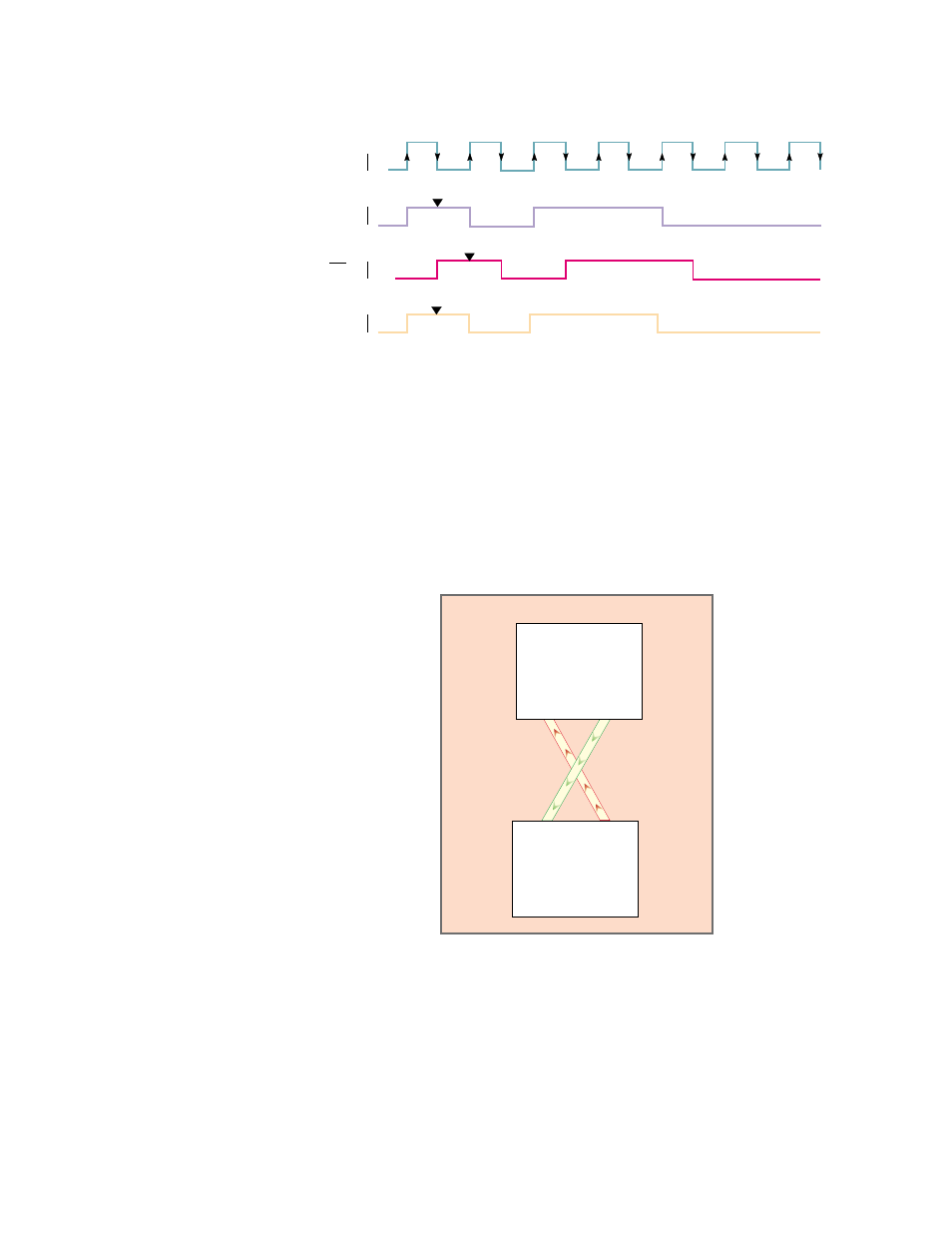
Crossover
Connection
Use a crossover connection whenever transmit and receive signals
go to the opposite leads for an application, such as tail circuits.
The receive data from device A becomes the transmit data to device
B. The receive data from device B becomes the transmit data to
device A.
In a crossover circuit, each DCE relinquishes control of the transmit
path to the other DCE. Clock signals are also cross-connected. The
DCE device outputs receive data at the rate which data is received.
See
.
Figure 2-8
Crossover Connection
Synchronous devices output a receive clock that is in phase with
receive data. Since receive data becomes transmit data to the tail-
circuit DCE, it uses the receive clock from the main circuit DCE to
sample correctly. In most crossover connections, both devices are
configured to use the receive clock as the transmit clock. The CSU
and DSU timing settings depend on the location of the master
clock.
Clock
Signal
ST
TT
ST
DSU
rx rd
tt td
DSU
rx rd
tt td