System fault isolation -19 – Verilink AS2000: The Basics (880-502981-001) Product Manual User Manual
Page 56
Hardware Installation
4-10
Verilink Access System 2000: The Basics
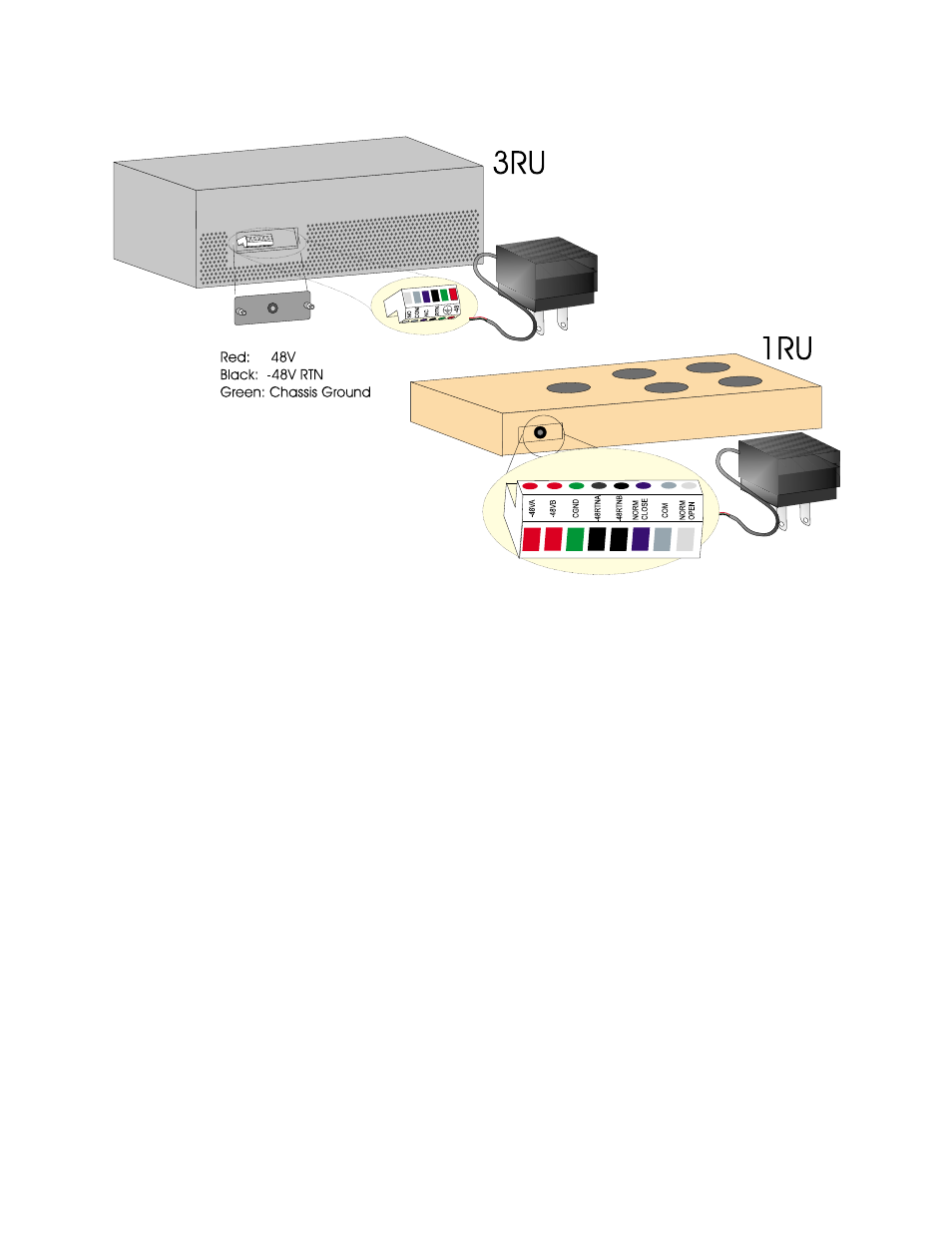
Figure 4-9 Connecting the Fan Shelf
DC Power Fan
Shelf Connections
To connect the cooling fan, to an MLS using DC power, refer to
and do the following:
1. Connect an 18-gauge wire from the fuse, to the Multi-line shelf
TB1 terminal block (pin 11), 48V (PD2930 power supply only)
position (pin 1).
2. If you are using backup power, connect an 18-gauge wire from
the fuse, to the Multi-line shelf TB1 terminal block (pin 12),
48V (PD2930 power supply only) position (pin 2).
3. Connect an 18-gauge wire from the fan terminal block ground
pin 4, to the TB1 terminal block ground.
4. If you are using backup power, connect an 18-gauge wire from
the fan terminal block ground pin 5, to the TB1 terminal block
ground.
5. Torque connector wire set screws to 4.5 to 8 inch lb (0.5 Nm to
0.9 Nm).