Watson-Marlow PD/40 User Manual
Page 12
12
•
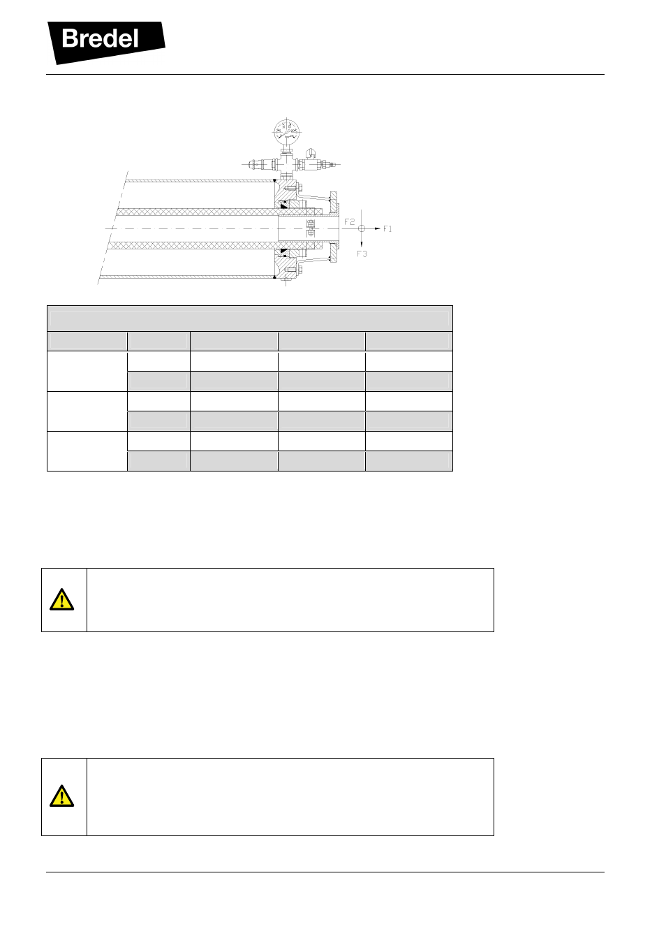
Avoid too heavy loads on the flanges. The maximum forces are given in the table below:
Maximum flange loads
Force
Unit
PD/40
PD/65
PD/100
F1
N
1000
1400
2000
lbf
225
315
450
F2
N
500
700
1000
lbf
112
157
225
F3
N
200
300
400
lbf
45
67
90
5.4
Lifting and moving the pulsation damper
To lift, move and position the pulsation damper, suitable hoisting belts must be used. The best place
to attach the hoisting belts is immediately behind both flanges of the pulsation damper. Keep in mind
the pulsation damper’s weight. For weights see also paragraph 8.3 Weights.
WARNING
If the pulsation damper is to be lifted, ensure that all safety regulations
for lifting movements are adhered to and that the lifting is carried out by
qualified personnel only.
5.5
Setting the pulsation damper pressure level for operation
The pulsation damper air or nitrogen pressure level must be set. This setting for maximum pulse
reduction depends on the process condition. Therefore the setting can only be obtained when the
pump is running at operating conditions.
It is advised to check the pressure relief valve functioning with each installation, hose replacement or
annually (which comes first). (See paragraph 6.4 Checking the Pressure relief valve.)
CAUTION
Consider the maximum allowable pressure. The maximum allowable
pressure can either be determined by the pulsation damper, pump or
process. Exceeding the maximum allowable pressure may lead to
serious injuries or damage to the pump and the environment.