Watson-Marlow PD/40 User Manual
Page 16
16
15. Pressurize the vessel to 1400 kPa (14 bar, 203 psi) above atmospheric. By pressurizing the hose
will be stretched outwards, forcing the hose ends over the inserts.
16. Close the ball valve.
17.
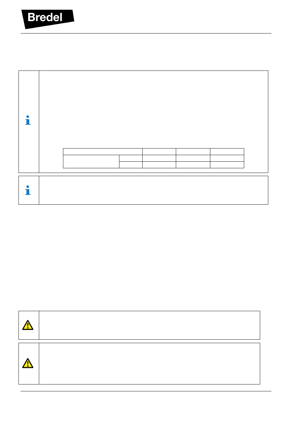
Tighten both hose clamps (pos. 8) with the proper torque values.
The minimum required torque values as advised (see paragraph 8.2 Torque values) can
not always be realized in the field. This is due to the unknown friction between tightening
bolt and clamp. Especially in case of used stainless steel clamps that are not properly
greased. In such case the applied bolting torque does not reflect the required clamping
force of the hose clamp.
So in case the minimum specified torque values are not sufficient it is advised to increase
the bolt torque until a sealed situation is obtained. Here the absolute torque value is of less
importance (although maximum applied bolting torques should remain within the range
specified (see paragraph 8.2 Torque values). It is advised to tighten the clamp until the
outside diameter of the clamp is between 0 to 2 mm (0 to 0.08 inch) below the outside
diameter of the PD hose in unclamped condition.
PD/40
PD/65
PD/100
Advised Clamp OD
[mm]
69 – 71
98 – 100
138 – 140
[inch]
2.72 – 2.80 3.86 – 3.94 5.43 – 5.51
The complete PD hose replacement procedure can also be done with the PD outside the
piping system, provided that the inserts are locked by installing an additional flange on both
sides of the pulsation damper flanges and external gas pressure (up to 1700 kPa, 17 bar,
247 psi above atmospheric) can be applied.
6.4
Checking the Pressure relief valve
It is advised to check the pressure relief valve functioning with each installation, hose replacement or
annually (which comes first).
1. Check all parts to be installed for any damage and replace when necessary.
2. Make sure the pulsation damper is fully assembled and installed in the process piping. (If testing is
done with a stand alone pulsation damper the inserts should be blocked by fitting additional
flanges on both flanges of the pulsation damper.)
3. Apply pressure to the pulsation damper by carefully opening the ball valve. The procedure for
applying the pressure is described in the paragraph “Setting the pulsation damper pressure level
for operation”.
4. Around 1700 kPa (17 bar, 247 psi), the pressure relief valve should open, keeping the pressure
from rising further. The proofs the relief valve is fit for duty.
CAUTION
Do not pressurize the pulsation damper if the inserts are not secured. Securing the
insert can be done by installing an additional flange on both flanges of the pulsation
damper or by installing the pulsation damper into the pipe system.
CAUTION
If you want to check the function of the pressure-relief valve, apply pressure to the
vessel just over the maximum allowable working pressure of 1600 kPa (16 bar, 232 psi).
The valve should automatically open. If not, do not apply more than 2300 kPa (23 bar,
334 psi) to the vessel, relieve the pressure and replace the pressure-relief valve if it
does not open before reaching 1900 kPa (19 bar, 276 psi) pressure