Instruction handbook, 9interface and change of voltage – Watson-Marlow PD12I User Manual
Page 17
INSTRUCTION HANDBOOK
PD12I / PD12P
PD12IP IH 1.03 EN
Version: 1.03
Page 17 of 20
9
Interface and change of voltage
9.1
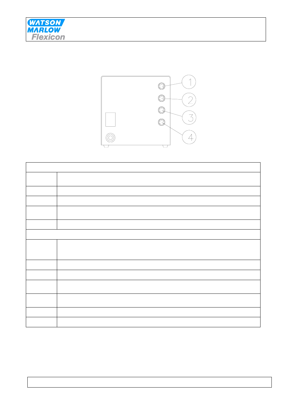
PD12 I Interface
Fig. 9.1
(1) External 1:
PIN 1:
INPUT FOR START SIGNAL
+5 - 50 VDC, min. 100 msec. positive-edge-trigged.
PIN 2:
OUTPUT, +24 VDC, MAX. 500 MA.
PIN 3:
GROUND.
PIN 4:
STATUS OUTPUT, MAX. +24 VDC, 100 mA.
Pin 4 is grounded via an open collector during filling.
PIN 5:
STATUS OUTPUT, MAX. +24VDC, 100 mA Pin 5 is complementary to pin 4.
(2) External 2:
PIN 1:
INPUT FOR DISABLING.
+5 - 50 VDC. if this pin is activated, the drive will be disabled (no
dispensing).
PIN 2:
OUTPUT, +24 VDC, MAX. 500 MA.
PIN 3:
GROUND.
PIN 4:
STATUS OUTPUT, MAX. +24 VDC, 100 MA.
Pin 4 is grounded via an open collector during filling.
PIN 5:
STATUS OUTPUT, MAX. + 24 VDC, 100 MA.
Pin 5 is complementary to pin 4.
(3) Net 1 This socket is reserved for (RS-485) network communication.
(4) Net 2 This socket is reserved for (RS-485) network communication.
Tab. 9.1