Instruction handbook – Watson-Marlow PD12I User Manual
Page 7
INSTRUCTION HANDBOOK
PD12I / PD12P
PD12IP IH 1.03 EN
Version: 1.03
Page 7 of 20
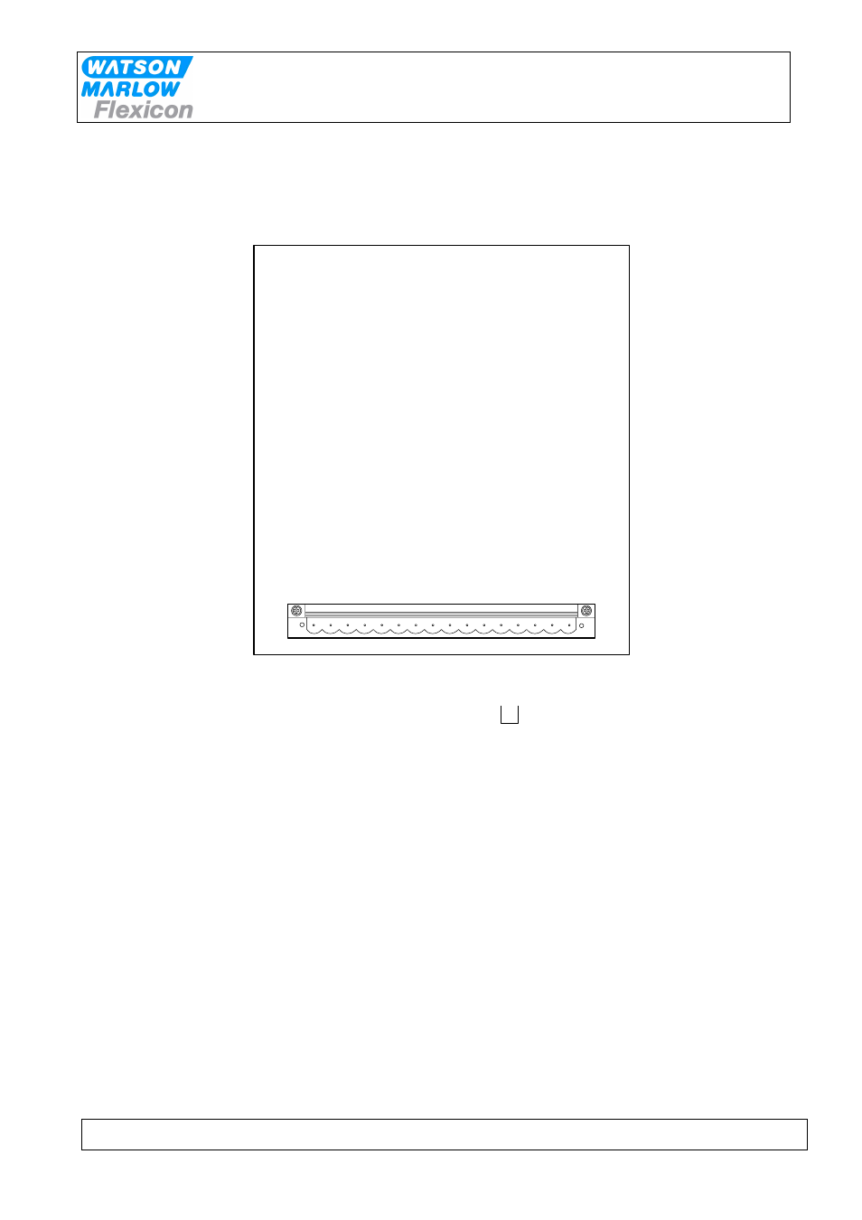
3.3.2 PD12P Installation
PD12P must be placed either in frame delivered or otherwise in a suspension frame.
All electrical connections are on the rear side.
1 2 3 4 5 6 7 8 9 10 11 12 13 14 15 16
Flexnet
1 - 3
External 2
7 - 9
Prime
10 - 11
Safety
12 - 13
Mains Power
14 - 16
External 1
4 - 6
Short Circuit
Fig. 3.2
The power supply is mounted with 0 in pin 14, earth in pin 15 and phase in pin 16.
The communication cable from MC12P is mounted in pin 1-3.
Should the system be operating more than one PD12P, the communication lines are
connected in parallel in pin 1-3 in all units.
Address "1" is the factory setting of PD12P. In case you want to change this setting, please
consult section 3.4 in this manual.
PD12P is now ready to be switched on and to be programmed from the MC12P.