Rs-232 – Westermo MR-2x0 User Manual
Page 14
14
6622-2221 • -29000447
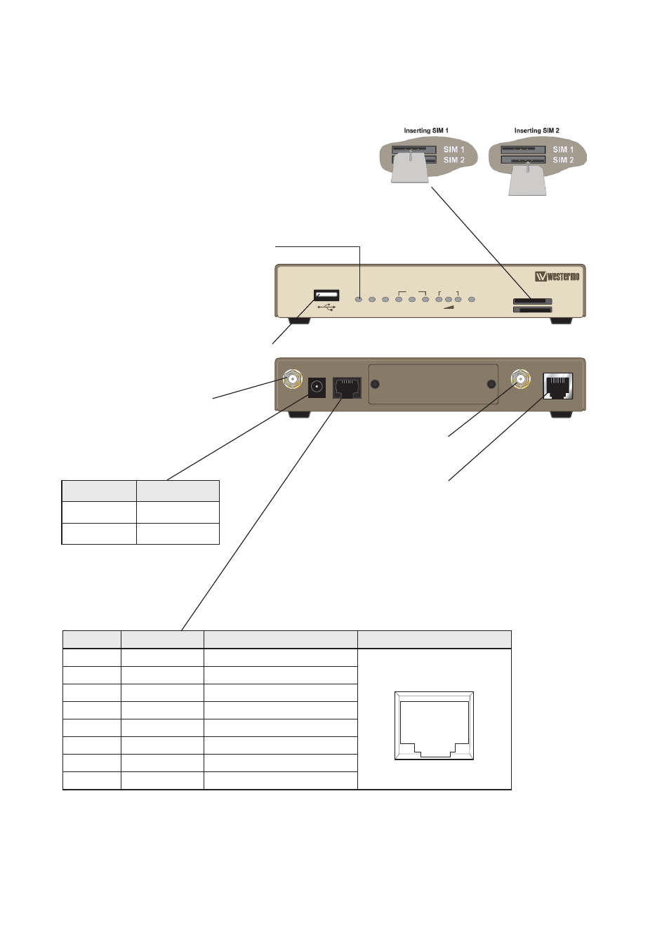
RS-232
Position
Direction
Description
Connector Description
No. 1
In
RTS (Request To Send)
1 2 3
4
5 6 7 8
No. 2
In
DTR (Data Terminal ready)
No. 3
Out
RD (Receive Data)
No. 4
–
Not Connected
No. 5
Not connected
SG (Signal Ground)
No. 6
In
TD (Transmit Data)
No. 7
Out
DCD (Data Carrier Detect)
No. 8
Out
CTS (Clear To Send)
ANT.
(AUX.)
9-48V
DC
ASY 0
ANT.
(MAIN)
LAN
MR-210
PWR LAN WAN NET
SIM
DAT
DTE
SIM 1
SIM 2
GPRS
SIGNAL
Antenna interface
Connections, MR-210 and MR-260
Ethernet interface
USB Host Connector
LED Indicators
(for details
see page 18)
Power interface cord
Cable
Description
Black
– VDC
Red
+ VDC
Antenna interface
(Not fitted on MR-210)
SIM Card Sockets
The two sockets at the left side of the front panel are for the GSM SIM card(s)
that you will receive from your service providers. SIM 1 and SIM 2
cannot be used to access two networks simultaneously.
The SIM card(s) should be inserted into SIM cardholders on the
right of the front panel as illustrated below.
In both cases, the end of the SIM card with the chamfered corner
should be inserted first. For SIM 1 the contacts should be face
down. For SIM 2 the contacts should be face up.