Westermo MR-2x0 User Manual
Page 16
Advertising
16
6622-2221 • -29000447
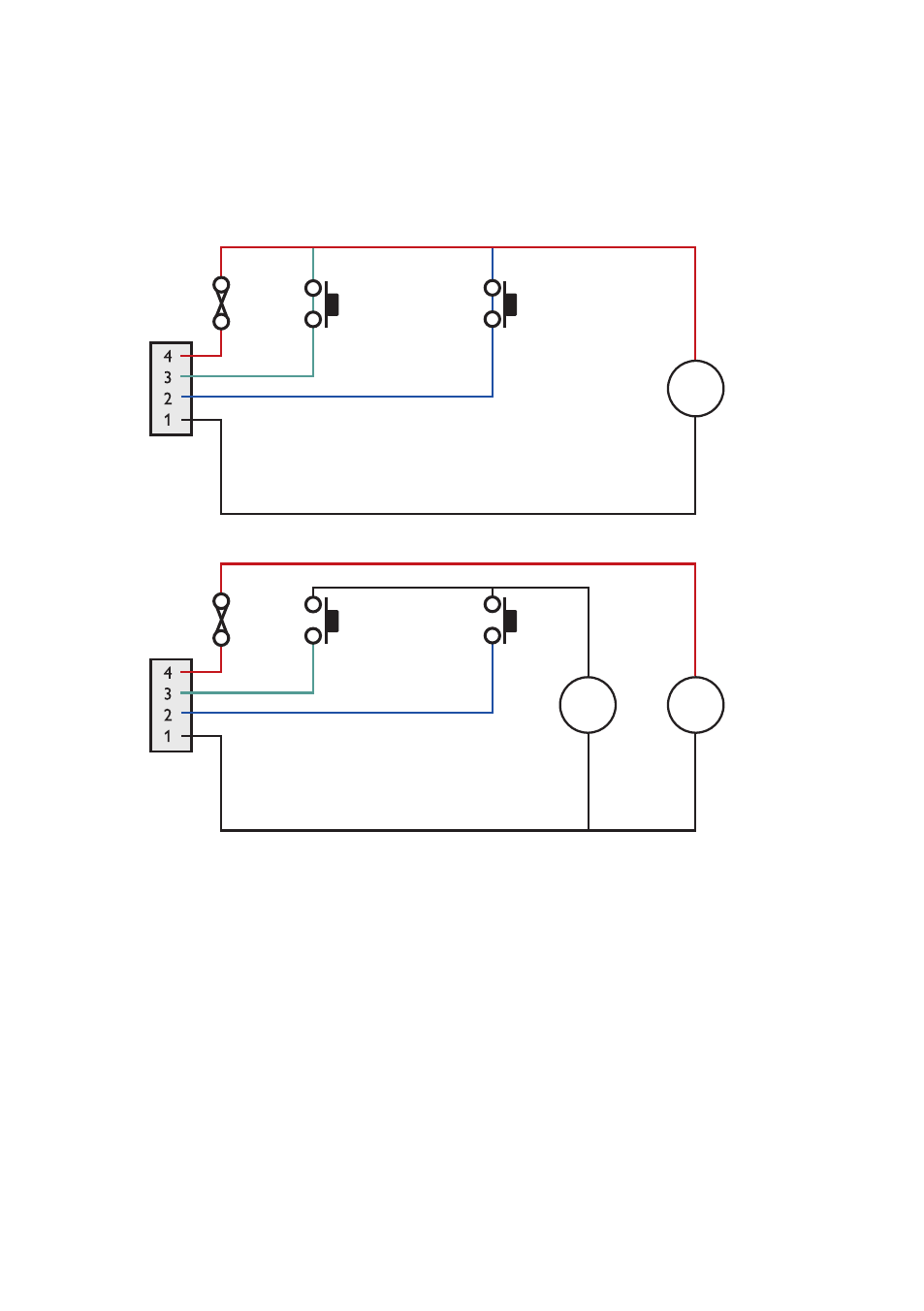
Description of AUX-connector and I/O signal lines
The auxiliary power connector has two programmable signal lines. One is an input line,
the other can be configured as either an input line or an output line. The mode of opera-
tion of the input/output line is configurable through the CLI.
The signal lines can be wired as shown in the following diagrams
POWER
11 – 28 V
Switch
Switch
INPUT/OUTPUT
INPUT
GND
+
–
POWER
Switch
Switch
INPUT/OUTPUT
INPUT
GND
11 – 28 V
+
–
4 – 28 V
+
–
2 Inputs, Supply Voltages up to 28 VDC
2 Inputs, Supply Voltages up to 58 VDC
Advertising
See also other documents in the category Westermo Equipment:
- TR-36B (88 pages)
- TD-36 (44 pages)
- TR-36 (36 pages)
- TR-36B (20 pages)
- IDW-90 AT (97 pages)
- GD-01 (20 pages)
- GD-01 (206 pages)
- MRI-128-F4G (175 pages)
- MRI-128-F4G (169 pages)
- GDW-11 (40 pages)
- GDW-11 485 (380 pages)
- Lynx Series (28 pages)
- ODW-720-F2 (36 pages)
- ODW-720-F1 (20 pages)
- ODW-720-F1 (24 pages)
- ODW-730-F1 (24 pages)
- ODW-730-F2 (36 pages)
- DDW-120 (24 pages)
- DDW-226-EX (24 pages)
- DDW-226-EX (24 pages)
- DR-270 (28 pages)
- DR Series (460 pages)
- ED-2x0 (20 pages)
- MRD-3x0 (199 pages)
- FD-80 (24 pages)
- FDV-206-1D-1S (24 pages)
- GD-01 US (24 pages)
- LD-01 (8 pages)
- IDW-90 (44 pages)
- Lynx-x10-F2G (16 pages)
- Lynx-x08-F2G-S2 (20 pages)
- MDI-110-F3x (16 pages)
- ODW-642 (28 pages)
- PII PoE Injector (12 pages)
- Viper Series (977 pages)
- SDI-5xx (12 pages)
- RFI-xx (32 pages)
- SDI-8xx (16 pages)
- RFIR-xxx (24 pages)
- TD-29 (16 pages)
- SDW-5xx (24 pages)
- TD-23 (24 pages)
- TD-29P (16 pages)
- Viper 408 (20 pages)